Control
Line Speed always seemed like a great aspect of competition to get involved in,
but like so many others, I just never made time for it. There are some really cool
videos on YouTube of C/L Speed models being flown. On a properly adjusted engine,
you can hear the engine break into a screaming 2-cycle mode after the airplane picks
up some speed and the propeller unloads a bit from the pilot whipping it. It is
like seeing / watching the afterburner kick in on a jet engine! A major change in
the design of Speed models from the 1955 vintage of this "Monitor" is the use of
a wing only on the inside. Rules require a minimum span and projected area, so putting
the wing on the "slow" side achieves the goal. I would love to have witnessed the
first time some guy presented his model to a judge with the wing only on the inside
and smiling as he challenged said judge to show where the rule book says the wing
must be on both sides of the fuselage.
This video is Paul Eisner, from Surrey, United Kingdom, showing the setting of
an F2A 2.5 cc world record for Control Line Speed. Listen to that engine!
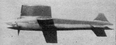
Two-Line Speed Plane: The 160.5 mph "Monitor" National Record
Holder
By Leland S. Morton, Jr.
My modeling career started at an early age with
rubber power models; I started flying free flight gas models in 1939. Then when
U-control came along I learned how to fly an original speed ship with an Ohlsson
.23 engine with a top speed of 60 miles an hour. Later, finding Fireballs and my
own designs more enjoyable to fly, I learned stunt and precision while working in
a hobby shop. As contests became more numerous I flew stunt at most of them, winning
a few trophies and engines. Then combat became the thing. I did very well in combat
but lost too many airplanes.
What led me to building the "Speed Monitor"
was my last combat ship. Considerable design and construction hours were put into
it and at its first contest it was completely destroyed - unnecessarily. I was very
discouraged, so I built speed ship #13 using some original ideas that didn't jibe
with the experts.
This is the plane that "Doesn't Have It!" By that I mean
as far as possible anything that would tend to hold it back was eliminated.
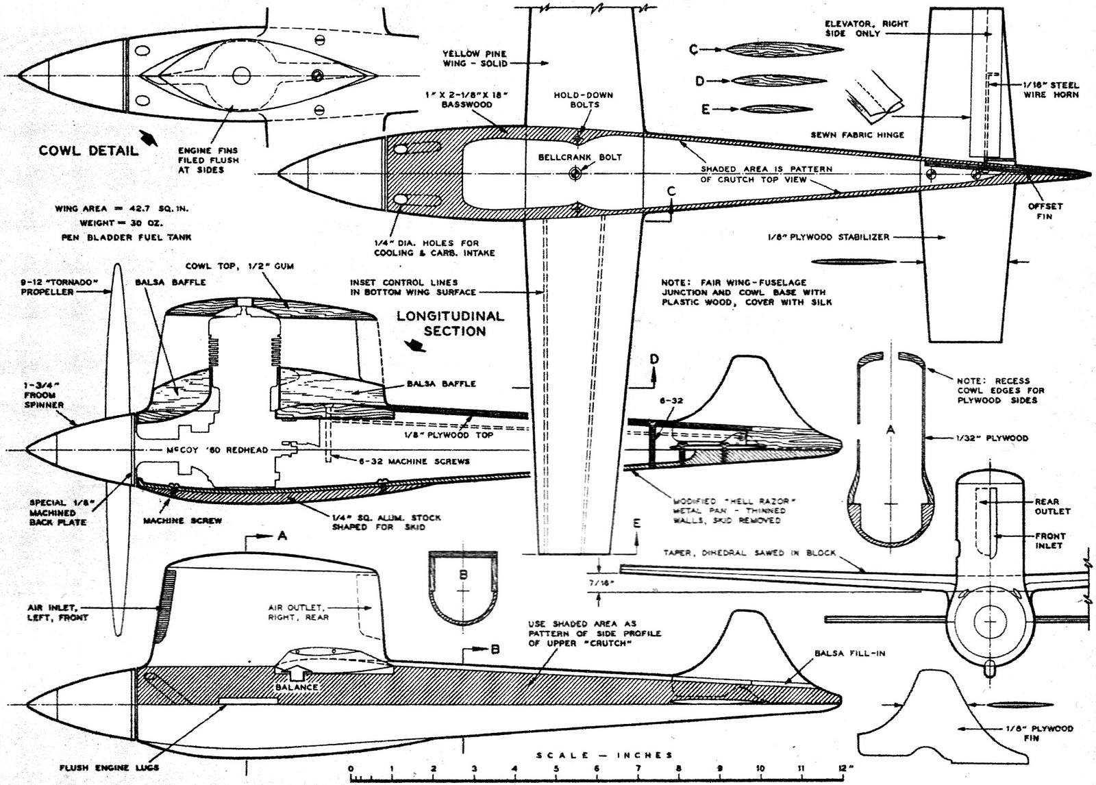
It features a "pressure ease" cowl based on a theory that if properly channeled
there is enough ram air to cool the engine, eliminate hot spots and prevent air
from stacking up in front of the cowl. The engine is a stock engine and the fuel
was stock fuel ("This-Is-It" hopped up). The prop was a stock 9/12 Tornado. The
engine was Liqua-Moly treated before it was run. First flight right out of the box
was 155.11, which broke the national record. Second flight was 153 at the first
record trials held in Dallas. It wasn't flown at the second record trials because
of the weather. At the third trials held February 21, it turned 156.32 first flight
and 160.51 second flight with a stock 9/12 Tornado and stock fuel pepped up a bit.
The construction method is not new inasmuch as crutch types have been used some
15 years or more. It is, however, entirely hard wood except the channeling inside
the cowl which is balsa. You start by grinding the fins off on each side of your
engine until they are flush with the outer screws in the head, covering up and protecting
the engine where necessary. This is done to reduce frontal area.
A Hell
Razor pan was used, and modified by cutting rear skid off and filing all excess
metal off. The engine was then mounted. A 1-3/4 Froom spinner was used with a 1/8
back plate turned on a lathe to keep it from binding on the fuselage when you tighten
the prop. The fuselage top was sawed out to the shape of the pan, using a piece
of basswood 3/4" x 2 1/2" X 18"; then sawed to take engine.
Next the wing the
wing was laid out; the dihedral was cut with a hand saw before laying out the outline.
The airfoil is a perfectly symmetrical section which according to theory flies at
a slight positive angle of attack. I couldn't find anyone who could measure it while
it was flying 155.11 or 160.51, so theoretically it's inefficient, but there was
no "lift" holding it back.
The rudder was made of 1/8" plywood and offset 3 degrees to help follow the circle.
Fuselage top was planked with 1/8" plywood extending from the two-thirds point on
the wing to about midway of the rudder. The remaining distance was filled in with
scrap balsa because of working ease. The elevator was 1/8" plywood; both elevator
and rudder are symmetrically shaped. The cowl sides of 1/32" plywood are glued to
the top of the fuselage and wing. The balsa channeling was put in before the top
(which is recessed) was glued in place. Be sure and tape your cylinder head with
about a 1/64" layer of masking tape to give side clearance when fitting. After the
cowl is finished carve the front of the fuselage to fit the spinner, tapering up
into the cowl.
Plastic Wood was employed to make fillets on cowl and wing. Cover all fillets
with raw silk.
Finish as desired.
Monitor Plans
Full- size plans for Speed Monitor are part of Group Plan #55 A from Hobby Helpers,
770 Hunts Point, New York 59, N. Y. (50¢)
Posted March 8, 2014
About Airplanes & Rockets
Kirt Blattenberger
Even during the busiest times of my life I have endeavored to maintain some form
of model building activity. This website has been created to help me chronicle my journey
through a lifelong involvement in model aviation, which
all began in Mayo,
Maryland...
Copyright 1996 - 2026
All trademarks, copyrights,
patents, and other rights of ownership to images and text used on the Airplanes
and Rockets website are hereby acknowledged.
 My modeling career started at an early age with
rubber power models; I started flying free flight gas models in 1939. Then when
U-control came along I learned how to fly an original speed ship with an Ohlsson
.23 engine with a top speed of 60 miles an hour. Later, finding Fireballs and my
own designs more enjoyable to fly, I learned stunt and precision while working in
a hobby shop. As contests became more numerous I flew stunt at most of them, winning
a few trophies and engines. Then combat became the thing. I did very well in combat
but lost too many airplanes.
My modeling career started at an early age with
rubber power models; I started flying free flight gas models in 1939. Then when
U-control came along I learned how to fly an original speed ship with an Ohlsson
.23 engine with a top speed of 60 miles an hour. Later, finding Fireballs and my
own designs more enjoyable to fly, I learned stunt and precision while working in
a hobby shop. As contests became more numerous I flew stunt at most of them, winning
a few trophies and engines. Then combat became the thing. I did very well in combat
but lost too many airplanes.