|
The term "gas" when
referring to miniature 2-cycle internal combustion engines (ICE) for model
airplanes, boats, cars, and helicopters, has its origin in the early days of
modeling. Similar to full-size automotive gas engines, they ran on gasoline, and
used a spark plug with a high voltage power source and timing mechanism that was
an integral part of the engine. As with a lawn mower or outboard boat engine,
timing of the spark relative to the position of the piston in the cylinder is
critical for optimum performance. Tuning the system could be a real challenge if
inferior gas was used, the spark plug was worn or dirty, or the spark generator
/ timing was poorly designed or faulty. Inherent engine design features like
intake and exhaust port timing, moving parts tolerances, and proper cooling
affect the performance, as they do also in glow fuel engines. Glow fuel engines
have the advantage that there is no timed ignition system to worry about since
the heat from fuel detonation keeps a nichrome coil of wire red- or orange-hot
enough to ignite the fuel/air mixture. "Glow" engines replaced gas engines in
popularity for many decades beginning in the 1950s, a while after this 1941
Flying Aces magazine article appeared. Gas engines are now back in vogue,
maybe more so than glow engines, now that electric motors dominate the model
landscape and glow fuel is horrendously expensive to use. A trend toward larger
models has also motivated gas engine use because a glow engine which would
produce the necessary power would require a fortune in glow fuel to run.
Trouble-Shooting a Gas Motor
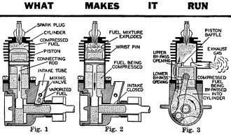
Skilled engineers and model designers combine their talents to
develop precision power plants. But these mechanical mites need your loving care
to assure their steady operation at all times.
by George T. Wieder
It never fails! Every time there's a big gas model contest, some of the most
promising entries never get off the ground. Yes, it's the same old story. The darn
engine won't turn over. And you cuss and kick plenty.
Well, I don't blame you. I've been in the same spot myself. A swell ship, gliding
angle as flat as a billiard table, and a soarer that would make an albatross look
like a sparrow by comparison. But my model just wouldn't fly that day - the engine
fell down on the job. That's what I thought. But I was wrong. How could it? It was
a brand new engine; I certainly paid enough for it. Now I know why - listen ....
In my anxiety to get the ship readied for the meet, and paying more attention
to its exterior finish, I neglected to give the engine the proper attention. By
that I mean the break-in run, use of the manufacturer's specified fuel mixture,
time spent in getting acquainted with the engine itself, taking the usual precautions
against improper operation, etc. I think I lost my chances of taking first place
at that meet. Well, believe me, never again. The engine is so important. Ask any
airplane mechanic.
My subsequent experiences with model gas engines have convinced me that in spite
of the precision mechanism and extent of perfection the gas engine has reached at
this time, they are bound to act erratic at times and go on the "fritz" for seemingly
no reason at all.
Well, there's a reason for most everything. But there's no reason why a good
gas modeler like yourself should experience engine trouble more than once.
The model plane gas engine has achieved a point of perfection at this time which
is amazing. Considering the short time in which it has reached this state, its limits
seem to have no bounds. But getting back to our original thought; the engine is
a mechanical storehouse of concentrated power and we want to get the most out of
that power in the short space of time allotted to us by the rules of contest or
action of our electrical timer. How are you going to do it? The method is simple.
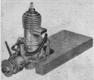
No. 1: The Comet "35" on its testing block.

No. 2: Position of the timer lever shows movements required for
retard, "A", advance, "B", and for maximum power, "C".
First, let's assume you've completed your gas job, moreover, let's assume it's
the first gas powered ship you've built. You have the engine. All right, take it
out of the box. Things look complicated, don't they? Wires, fittings, terminals,
coil, condenser. Perhaps your engine comes already mounted on a wood test block
such as the Comet "35" engine shown in photograph No. 1. Some engines do not come
in this manner but it is a simple matter to obtain four fair sized wood screws and
fasten it down securely on a block thick enough to withstand the pressure of its
being held in a vise.
Second, flatten out the pages of your engine instruction pamphlet which gives
a diagrammatic layout of the wiring set-up of the ignition system. Nothing complicated
about this. Study it carefully.
Take each strip of wire attached to your engine, and following the layout of
the, diagram attach each wire connection to its counterpart. This is just a temporary
measure to help you to familiarize yourself with the various electrical extensions.
After becoming accustomed to the "maze of wires" the next step is to solder on
all required connections. If you haven't handled a soldering iron before, this is
the time to learn. What is to be done is quite simple and one doesn't have to be
a tinsmith to know how.
A fairly good soldering iron can be purchased in the five and ten cent store
to serve the purpose. Make sure the iron has sufficient heat to make the solder
flow freely. Resin core solder is best suited for your need and should be purchased
at the time you get the iron. The parts to be soldered should be, first of all,
spotlessly clean throughout.
Don't attempt to split the wires and twist them around terminals in soldering.
Split the wire and clean the strands. Lay them flat against the top of the lug.
By holding the iron above the units to be joined (as shown in Step 1 of the drawing,)
the solder is allowed to flow freely over the connecting area.
When a sufficient quantity has gathered and cooled, the iron is then held below
the joint and the excess solder permitted to be drawn through the connection to
the iron. This makes a perfect joining of the wire, or wire strands to the lug,
void of excess solder as shown in Step 2. The same technique is followed all the
way through wherever soldering is required. A point to remember, how-ever, is that
in determining the length of the wire connections to be soldered, use the shortest
possible length. The shorter the distance from the batteries the hotter the spark.
For test-running obtain two booster batteries, the type used for doorbell purposes
and hook them up in the proper series. The correct method is shown in photograph
No.3. Note where positive and negative battery leads connect. Your wiring diagram
explains this clearly. A set of alligator clips should be used temporarily to make
connections between the ground and the coil. It is not absolutely necessary, however.
It merely provides an unshakable grip while the engine is being tested with boosters.
Later, the wire lengths should be soldered to lugs which are in turn soldered to
the aforementioned fittings permanently. Make sure your batteries are fresh. In
fact ask for an ammeter test. Your batteries should charge 25 to 35 amperes.
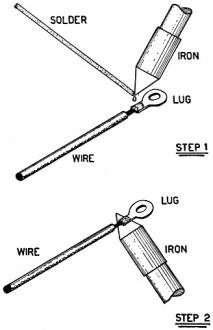
Soldering the ring terminal onto the ignition wire.
Now mix the correct fuel mixture called for in your direction sheet. Don't, under
any circumstances, use any kind of oil other than specified by the manufacturer.
His reason for specifying same is determined by test. The high temperature created
inside the cylinder calls for a special weight and consistency both for its cooling
and lubricating value. Most mixtures consist of three parts of white gas to one
part of SAE 70 oil. Fill your tank with this formula or any other formula required
except castor oil.
To start your engine, retard the spark lever. In photograph No. 2 the position
is shown by "A". All model gas engines operate practically the same and so the spark
lever may be manipulated in the same manner. Screw the needle valve down as far
as it will go without forcing. According to your instruction pamphlet, you'll have
to open the valve perhaps two or three turns.
Place your finger over the intake opening (located in various places on other
engines) and flip the propeller smartly for one complete revolution. Then remove
your finger and twist the prop until the engine starts. As the engine starts, slowly
screw the needle valve, as instructions call for, to what should be the smoothest
operating position. It is best to adjust the needle valve back and forth to find
the best spot.
Advance the timer (spark lever) slightly closer toward the center (position "B"
in photograph No.2) to increase the speed but do not extend the arm beyond that
position at anytime during the breaking-in period. Breaking in the engine properly
usually takes 4 to 5 actual running hours. It is suggested that a notebook be kept
and the time logged every time the engine is run. Run the engine at least a half
an hour at a time allowing as much time for cooling. A completely broken in engine
consumes anywhere between 120 to 150 tank-fulls of gas.
When the engine is thoroughly broken in the timer lever may be moved to dead
center or as in the case of the engine shown in the photo No.2, position "C". The
position varies in some cases. Only by cautious manipulating can you get the feel
of power. Instruction facts supplied with each motor give the position of the timer
lever for maximum power.
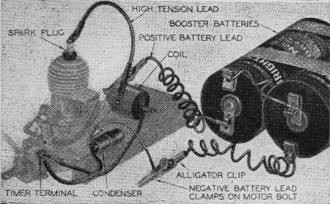
No. 3: Use booster batteries for break-in run. Note the correct
method of wiring.
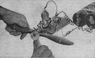
No. 4: The propeller is bolted on tight in a horizontal position
as the piston starts up to the top of cylinder. It makes for easier starting.
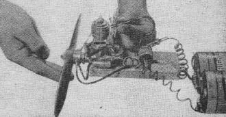
No. 5: To check spark, hold the high tension lead as shown.
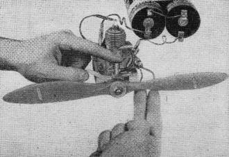
No. 6: To start engine, place finger over intake opening and
turn prop only one complete revolution.
Remember, there is no way in which you can hasten the breaking in period of your
engine other than the method described above unless you want to injure your motor.
You'll be paid with extra power, longer life, and freedom from annoying troubles
in proportion to the amount of care you use during the wearing in period of engine
operation.
The foregoing has undoubtedly acquainted you thus far, with the ignition hook-up
and breaking in of the engine. After this period, the engine is installed in your
ship, and glide tests begun.
No doubt about it, in due time you're going to enter your ship in a local contest,
By this time you should be well familiarized with the engine mechanics. But as said
before, little troubles crop up when you least expect them and they seem to happen
just as your time nears to send the ship off on an official flight.
What to do. Suspicion is centered everywhere when the engine displays a balky
temperament and in your confusion you don't know where to start trouble-shooting
first.
Alright then, let's look at the ignition system first. Three-quarters of engine
failure can be attributed to ignition failure due to a faulty spark plug connection,
battery hook-up, or wiring. So let's first examine all the soldering connections.
Assuming the soldering joints are Okay, take a clean cloth and thoroughly wipe
them clean of the excess oil which is constantly being thrown off from the engine.
Check the bolts which hold the engine down on its mounts. Loose bolts frequently
cause poor spark delivery. Tighten securely. Now then the spark. If there is no
spark, this trouble can be traced to weak batteries, burnt out coil, or condenser.
Let's check the plug first.
Remove tile plug carefully and place it against the cylinder where it is grounded.
Turn the prop over several times and watch for a spark to jump the gap between the
electrodes. A healthy spark is large, intense, of a bluish white hue. If it is thin
and weak we can trace that to the battery or batteries which are just about ready
to "give up the ghost." Replace the batteries with a fresh pair and systematically
check the next contact point. Perhaps the trouble may lie in the coil.
To find out for certain, use your set of large boosters. Hold the high tension
lead between your thumb and forefinger and spin the prop smartly. A healthy shock
will convince you that there's no trouble around this part. If the coil fails to
deliver a spark after turning the prop over a few times then your coil is known
as "shot." Get a new one. A condenser in poor condition will cause the engine to
spit, sputter, and miss while it is trying to operate in spite of a healthy set
of batteries and good coil. Replace the condenser, too.
Try the timer points. The distance between contacts at their greatest openings
vary with certain types of engines. Dirt or oil accumulated in the contact points
lower the voltage causing less heat in the spark. Open the points, place a strip
of clean paper between them, close, and draw it out again. This should remove the
dirt. Washing with clean raw gas does the trick, too.
In the event that the points have become pitted from wear, they must either be
replaced or "filed" smooth with fine emery cloth. The contact should have flat surfaces.
Turn the crankshaft slowly and see if the timer points close once per revolution.
If they do not, adjust very carefully with the aid of a long-nose pliers to a gap
of about 0.015 inch and repeat the spark testing operation.
Should the testing prove that the batteries, coil, and condenser are sound remove
the plug and examine its electrodes. Excess carbon or oil can prevent its functioning
properly. Scrape the carbon off with a sharp blade. Clean with raw gas and a hard
bristled brush.
In adjusting the electrodes be careful inasmuch as they are made from hard material
and can be easily broken. To bring the gap closer bend only the curved electrode
leaving the center one untouched. Badly pitted points should be dressed up with
the aid of a file and rechecked with a spacing strip made of either thin cardboard
of the calling card variety or sheet metal. Since most electrodes are spaced at
0.010 inch it is best to carry a piece of such gage.
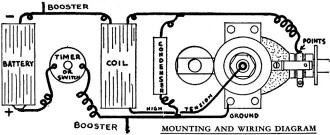
Mounting and wiring diagram.
If trouble-shooting the electrical system fails to bring out any fault with ignition
the next place to look for trouble is the engine itself. Lack of gas will, of course,
prevent the engine from getting its normal feed. Check the needle valve setting
unscrewed from a closed position and repeat the choking and starting technique.
If the engine still doesn't kick over, try priming by using an eye dropper and injecting
the fuel directly into the cylinder. Twist the prop over smartly.
If the engine gives a short high speed burst, open the needle valve; if short
low speed run, close the valve slightly. Flooding is caused by unscrewing the valve
too many turns from the closed position, or flipping the prop more than once while
the finger covers the air intake.
To remedy this situation, screw the valve to closed position and keep flipping
the prop 50 or 60 times until the flooded condition clears up and the engine begins
to fire. In bad cases, remove the plug and blowout the fuel which is undoubtedly
fouling it. Replace the plug after it is cleaned and repeat the starting operation
from scratch.
A loose spark plug will cause loss of compression and naturally makes the engine
hard to start. Tighten the plug until quite snug using a properly fitting wrench.
Don't use a pair of pliers. It might slip and crack the porcelain. Oil that is too
light for your type of engine will also cause loss of compression.
Your best bet is to purchase a full quart of the required grade. Strain it and
fill in small handy bottles. On the field, strain your gas before mixing with oil.
Taking ordinary precaution, studying the operation of your engine, you'll find that
even the most cantankerous engine will behave like a purring kitten.
|