 With the entry of the United States into World War II came the
need for service members to be trained on many new technologies - among them being
airplanes and the ability to identify them quickly. Electronics technicians and
airframe and powerplant mechanics were in need, of course, but everyone had to be
able to tell friend from foe when airplanes were approaching. In order to assist
the war effort, a call went out to civilians to begin producing thousands of models
at a 1:72 scale so that at 35 feet away they appeared in size to be that of a full-scale
version at about half a mile. Detailed paint jobs were not required - only that
the profile from all angles look exactly like the real thing. In fact, the models
were painted flat black so as to look like a distant airplane against the background
sky. Both Allied and Axis airplane models were needed so that soldiers and sailors
could quickly spot a potential danger and decide whether to take cover and prepare
to fight, or to continue with business as usual. This article appeared in the May
1942 edition of Popular Science, meaning that it was probably written sometime
around February, only a few months after the Japanese attacked our naval base at
Pearl Harbor, Hawaii, on December 7, 1941.
How to Make Scale-Model Planes for Government Use
 By Frank Zaic By Frank Zaic
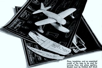
Plans, templates, and an unpainted model of the type to be used
for training fliers and plane spotters. Models must be finished dull black.
With 500,000 miniature planes required immediately for the training of Army,
Navy, and civilian personnel (see P.S.M., April '42, p. 79), and the likelihood
that still more will be required, every patriotic builder of models is likely to
ask, "What's needed and how can I do the job best?"
Full-size plans are to be distributed by local school superintendents, and there
are to be fifty different designs or plans in all, of which a typical one is shown
above. All models are to be built to a uniform scale of 1" to 72", so that 35' away
they will look exactly like their prototypes at a distance of a little less than
half a mile. The tiny craft will be subject to much handling and must be made of
substantial materials such as poplar, white pine. basswood, or whitewood. Models
made of balsa will not be accepted. Avoid using knotty or resinous wood. The glue
used should preferably be of the new resin type, and not ordinary model-airplane
cement, which tends to peel off when when used on close-grained material.
It is not necessary to have windows, propellers, and other small detail on these
models. Their purpose is to train air fighters and spotters to identify our own
and Axis ships at a distance half a mile by wing, tail, and fuselage outlines. Details
are not visible on a full-size plane at that distance and are therefore superfluous
on the models.
The first step in making any number of these models is to glue the full-size
patterns to a backing of sheet fiber or tin-can metal before cutting them exactly
to line. Both pattern and backing are then trimmed together. Such reinforced templates
may be used again and again.
The accompanying drawings illustrate the step-by-step procedure in building a
model of the Vought-Sikorsky OS2U-1 U. S. Navy Observation Scout. This involves
the making of a pontoon and two floats in addition to the fuselage, wing, and tail.
With a very sharp pencil, layout both side and plan-view fuselage profiles on a
squared-up block of suitable size, together with center lines on the top, bottom,
and ends, as In Fig. 1. While the blank is still square. saw out the wing and tall
slots, and drill the holes for the struts (Fig. 2). Saw the blank to the side profile
as in Fig. 3. Pin back the waste temporarily to make the work easier to handle,
and saw out to the top or plan view as shown In Fig. 4.
 Plans include cross-section templates, but instead
of using these merely to check the fuselage after shaping, inscribe the curve of
each within a drawn rectangle exactly the size of the hull cross section at that
particular station (Fig. 5). Against this curve draw tangent lines as shown. With
dividers or a scale, take off the intervals A, B, C, and D, and on the fuselage
blank scribe lines spaced at such intervals from the edges and center lines. Plans include cross-section templates, but instead
of using these merely to check the fuselage after shaping, inscribe the curve of
each within a drawn rectangle exactly the size of the hull cross section at that
particular station (Fig. 5). Against this curve draw tangent lines as shown. With
dividers or a scale, take off the intervals A, B, C, and D, and on the fuselage
blank scribe lines spaced at such intervals from the edges and center lines.
It is now easy to carve the fuselage roughly to shape (Fig. 6). Work down only
to the lines, keeping the carved surfaces perfectly flat. If you attempt to rough
out and round off at the same time, you will lose the guide lines.
When the fuselage has been roughed out all over, you are ready to carve it to
the initial shape. Use the templates freely as you work, and finally sand this part
smooth (Fig. 7).
To make the models capable of withstanding hard usage, the wing, tail, and rudder
must be securely attached. Cut the fuselage from the bottom up to the wing slot,
and from the top down to the tail slot as shown in Fig. 8. Save the pieces. Cut
the one from the tail in half lengthwise.
 Tail surfaces have thin, streamlined airfoil
sections. Merely rounding off the corners will leave the model looking like those
that are used to decorate barns. An easy way to shape tail and wing airfoils properly
is shown in Fig. 9. Tiny thumb planes will be found useful in beveling the surfaces
roughly to shape. Round off the corners and sand all smooth afterward. Use care
in cutting tall surfaces to shape, as planes can often be identified by these alone. Tail surfaces have thin, streamlined airfoil
sections. Merely rounding off the corners will leave the model looking like those
that are used to decorate barns. An easy way to shape tail and wing airfoils properly
is shown in Fig. 9. Tiny thumb planes will be found useful in beveling the surfaces
roughly to shape. Round off the corners and sand all smooth afterward. Use care
in cutting tall surfaces to shape, as planes can often be identified by these alone.
The stabilizer is glued to the flat of the tail slot. The plan shows the rudder
as it appears above the fuselage, but actually the rudder is cut longer so that
it may be glued to the top of the stabilizer. The two halves of the section previously
cut out are sanded to a good fit and glued in on either side to bring the fuselage
to shape and reinforce the rudder (Fig. 10).
Lay out the wing, including the center line and the two lines indicating the
dihedral break (Fig. 11). Cut to outline and shape to a true airfoil section as
in Fig. 12. Taper the wing toward the tips as called for in the plans. In some wings
the top is tapered toward the lower surface, but more often the lower one tapers
upward. Finish smooth with fine sandpaper.
The wings of modem fighting ships have a considerable dihedral angle. This is
best formed by making V-shaped cuts along the lines marked and raising the wing
tips until the wood just cracks but does not break off. Apply glue freely to the
v-cuts and place the wing in a jig (Fig. 13) to set. Check the dihedral, as given
by the gauge, against that shown in the projection drawings, as the template may
not prove accurate for so small a model.
 Pontoons and floats are made in the same way
as the fuselage (Figs. 14, 15, and 16). Pontoons and floats are made in the same way
as the fuselage (Figs. 14, 15, and 16).
Small struts should be made of a hardwood such as maple. Shape them to the correct
cross section shown in Fig. 17. Never leave them square or rectangular, or be content
with simply rounding the corners.
The center lines drawn on the nose are used in aligning the wing and mounting
the pontoon. Pin thin strips along them as shown in Fig. 17. Use these to sight
across as the plane is being assembled.
Glue the wing into the slot provided for it, and glue in the cut-out piece below
it. This is a stronger and easier method of mounting the wing than that of using
dowels or a butt joint. Do not worry about cracks left around the wing section in
the fuselage. These can easily be filled with glue.
The resin glue to be used is somewhat similar to casein glue, except that it
is mixed with less water and is ready for use immediately. It sets in a few hours.
If work is held near a radiator or left in a warm place, half an hour will suffice
for surface drying. Once the glue has set, the adjoining wood will rupture before
the joint itself. Within 48 hours the glue hardens to a rock-like consistency, so
be sure to work cleanly and leave none where it does not belong. If glue fillets
or the like are to be finished, sand them smooth within four hours.
 The models must be finished dead black, with
no gloss, like the inside of a camera. Poster color or flat black oil paint will
do. However, several thin coats of ordinary wood filler should first be applied
to close the pores. Sand the plane perfectly smooth afterward. When the surface
shows no grain, the black paint may be applied. Two coats should suffice. Paint
them on smoothly. The models must be finished dead black, with
no gloss, like the inside of a camera. Poster color or flat black oil paint will
do. However, several thin coats of ordinary wood filler should first be applied
to close the pores. Sand the plane perfectly smooth afterward. When the surface
shows no grain, the black paint may be applied. Two coats should suffice. Paint
them on smoothly.
If many of one type of model are to be made, jigs should be used whenever possible
- for obtaining the dihedral angle, in assembly, and for marking fuselage blocks.
The work should be divided so that those having power machinery can cut or rough
out parts, leaving finishing to those who can use only hand tools. A penknife, a
small drill, one or more thumb planes, and sandpaper comprise almost all the tools
needed for the final shaping, flitting, and assembly. The U. S. Navy, which sponsors
this model-building project has already sent plans for the Vought-Sikorsky and nineteen
other planes to participating high schools.
Retrieved article from
Google Books archive.
Posted March 12, 2024
(updated from original post
on 11/1/2014)
|

