|
For as long as I can remember, the instructions for assembling eyelets to control
line leadout wires has been the one depicted in the image to the right. It appears
to be a copy of a copy of a copy of a scanned image from a printed version of the
Academy of Model Aviation (AMA) rulebook. This particular rendition comes from the
"Control Line General 2017-2018" publication from the AMA (Figure 3.
Two-Line Construction, on page 8). Its simple
presentation is fairly easy to follow, but actually accomplishing the feat can be
a little tricky when using the multistrand steel leadout wire. I am no master of
the task, but have constructed many leadout eyelet ends in my six decades. A pictorial
representation of the process I use is given below. This is from my electric-powered
Jetco E−Shark 15 control
line model. Hopefully, you will find it useful.
|

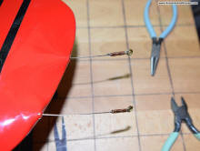
Here are the two completed leadout lines with eyelets assembled,
so you know where we'll be headed. Choose a starting point some distance from the
wingtip which allows full motion of the bellcrank.

Step 3 - Pass the free end of the leadout line back through the
crimp tube, forming a loop for the eyelet. Don't worry about the exact length at
this point.

Step 5 - Pull the leadout line tight around the eyelet while
adjusting the eyelet position to match the other eyelet. Don't worry about the other
end for now - just get the eyelet positioned and tightened correctly.

Step 7 - Finally, clip off the excess free end of the leadout
line. Done!
|

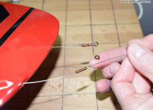
Step 1 - Here, the first eyelet is already installed. Block the
elevator at zero degrees of throw and find the point on the other leadout line equal
to the first eyelet.

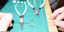
Step 2 - Slide the metal crimp tube over the line.

Step 4 - Now pass the free end of the leadout line back again
through the crimp tube. This is much easier than trying to hold the leadout line
tight around the eyelet while feeding the line back through.

Step 6 - Hold the eyelet and crimp tube securely while pulling
the free end of the leadout line back toward the eyelet until the other looped end
(closest to the wing) protrudes the prescribed distance (1/8") from the other end
of the crimp tube. Use a crimping tool or rounded pliers to crimp the tube tightly
in two location per the AMA instructions.
|
Posted July 26, 2019
|