|
I'm not sure how long the 3rd-line
for throttle control has been around, but this article from the August 1957 edition of
American Modeler seems to suggest that it was introduced formally around time of the
1957 model hobby industry trade show in Chicago - maybe a few years before. There in
an exhibitors' booth was a special bellcrank featuring a three-wire control line system
offered by the J. Roberts Model Manufacturing Company, of Baker, OR.
Third Line Theme
 The scene is the big annual trade show for
the model-hobby industry in Chicago. Three large halls are jammed with exhibit booths
of new plane, train, and boat kits, engines (glow) and motors (d.c.), accessory and supply
materials.
Sauntering about are fat-cat distributors and their coveys of salesmen, rival manufacturers,
solemn-looking designers checking the other guy's brainstorm -and almost lost in the
vast crowd, a few build-it-yourself control line modelers.
Although outnumbered a hundred to one, it's easy to spot the yo-yo fans. All you have
to do is plant yourself in front of the small display by a small concern from a small
town in Oregon. This booth features "Flight Control;" a three-wire control line system
offered by the J. Roberts Model Mfg. Co., of Baker, Ore.
Here come some CL'ers; quickly come their comments. "Hey, look at that landing gear
retract!" "Now that's what I call a real sharp motor control . . ."
 Etc., etc., etc. You get the idea. Etc., etc., etc. You get the idea.
What is this third line deal that's the theme of J. Robert "Bob" Smurthwaite's pitch?
Bob describes it as "a mechanical triple-control connection in which three wires can
be selectively manipulated while an equalizing pull or tension is exerted on all three."
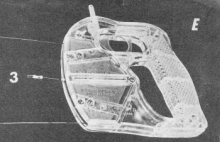
Translated from the Patent Office lingo it means you move the Roberts Flight Control
handle (photo E) like any standard Ukie handle for "Up" and "Down"; at the same time
you can trigger a third line back and forth. Different, claims JRS, is the fact that
the centrifugal pull of the airplane in flight is divided among the 3 control lines which
share equally the pull load.
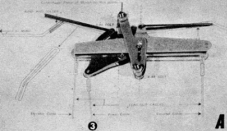
System consists of three lines (which you provide), the handle and the "Plane-Unit"
(photo A).
Lines hook up and detach in conventional manner for storing on any standard reel.
Most modelers are surprised to find no springs in the set-up. Reason; a doubled leverage
mechanism within the handle compensates for every action of the plane-unit regardless
of the maneuver or control operation.
 Consequently, as Smurthwaite points out, it requires
very little line tension to maintain full control. As a result solo flight operations
are possible. In fact, the first motor-speed control flight with the experimental unit
was a I-man deal from hooking up the lines, starting the engine, walking to the center
of the circle, then taking off the model. A spring held the motor speed restrictor at
low when the lines were slack. Consequently, as Smurthwaite points out, it requires
very little line tension to maintain full control. As a result solo flight operations
are possible. In fact, the first motor-speed control flight with the experimental unit
was a I-man deal from hooking up the lines, starting the engine, walking to the center
of the circle, then taking off the model. A spring held the motor speed restrictor at
low when the lines were slack.
This original test plane was a scale model of the Danish KZ-3 lightplane. The 5-pound,
54" wingspan model used a Madewell .49 on ignition. An exhaust rotary restrictor had
been installed in a stack extension. After 8 years of flying Bob's first all-aluminum
plane-unit is still in good condition. Its bulkiness has been cut down in the latest
version. Final tests are near completion on a small one for use on planes with motors
up to .15 cu. in. displacement. Regardless of the size of the plane-unit or model, the
one size handle works with all.
Ron Moulton, noted English designer, reported to Bob that "the great revelation was
that the control can be set and left alone. We had been under the impression that it
would be essential to maintain finger tension on the 3rd line to retain engine setting,
but in fact, this is only required when ... (one) blips the motor ... "
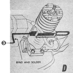
Shown
in sketch D is the new style full-length "slide-restrictor" Smurthwaite now recommends.
This type which fits almost every size and shape exhaust stack works more smoothly and
wears longer with its lengthened, edge surfaces. You make this by drilling starting holes
in the saw blade "slide" material and filing out the open "port." It is best to grind
and fit the blank slide to the necessary incisions and tracks that you make in the exhaust
stack before drilling and porting the slide. Your motor, naturally, starts each time
with restrictor slide back in open, full-speed position.
The Oregon manufacturer sees the Navy Carrier, the new Air Force Rocketry event (AM,
pg 42, 2/57) and rat racing as logical places for his units. Beyond that he
thinks motor speed control and wheel brake possibilities will stimulate greater activity in all phases
of control line flying be it sport or com-petition.
"In recent years," declares JRS, "precision aerobatic events have been won by
flyers who enter large models with stunt flaps in the wing. A smaller
precision-stunt model utilizing Flight Control will wrap up more points than
ever before possible with the following advantages: The necessity of stunt-flaps
to perform those square comers can be eliminated by the combination of a
full-power ,surge and up/down elevator control
at: the same moment to snap the plane around sharply. Smaller models can be slowed to
a smooth cruising speed between each maneuver to allow the judges more time to record
maneuvers.
 "By smaller model, I refer to a model without stunt-flaps
with a span between 38 and 46 inches and a wing area from 320 to 450 square inches." "By smaller model, I refer to a model without stunt-flaps
with a span between 38 and 46 inches and a wing area from 320 to 450 square inches."
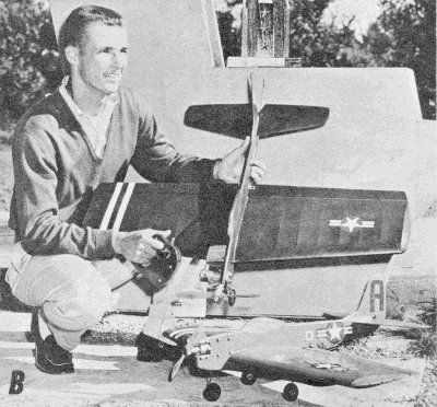
Production-line control units were first used at the Dallas National Meet last July.
Donald Storner (photo B), 15, of Belleville, Ill., won first in Junior Navy Carrier using
Flight Control to operate a Bramco throttle on a Fox 35 motor. His friend from Belleville,
16-year-old John Corrough, won second in Senior Carrier event with the same combination-both
flew J. Roberts "Sabre" models equipped with their own version carrier-hooks. John's
model is shown on ground in photo B.
Glen Magree of Cleveland took first in Senior Carrier using Flight Control to operate
a Roto-valve on the Fox 59 in his scale model "Bearcat."
Besides the. items mentioned JRS says his system can be utilized to operate landing
flaps, carrier-arresting hooks, bomb-bay doors and racks and related mechanism to drop
any desired number of bombs at any time from any position including dive-bombing, also
multi-engine control, landing lights, pilot ejection seat, even change of propeller pitch.
 Bob is an old-time modeler having been a fan of this
magazine since its Bill Barnes days. He recalls building from our early plans Gordon
Light's 1935 Wakefield winner and Al Judge's '36 championship plane as wen as many of
Alan Booton's scale jobs. As owner of one of the first Ohlsson .23 power plants, he scaled
down Ben Shereshaw's Cavalier to take that engine. Bob is an old-time modeler having been a fan of this
magazine since its Bill Barnes days. He recalls building from our early plans Gordon
Light's 1935 Wakefield winner and Al Judge's '36 championship plane as wen as many of
Alan Booton's scale jobs. As owner of one of the first Ohlsson .23 power plants, he scaled
down Ben Shereshaw's Cavalier to take that engine.
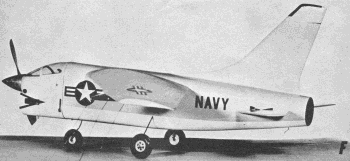
Bob's forthcoming kit models includes a scale-line prop-driven Crusader (pho-to F)
for Navy Carrier and other racing events. Span is 28", length is 30"; it takes .29 to
.35 motor. Original has carrier-hook; complete horizontal tail surface moves like the
full scale job. All-balsa molded construction to be featured; kit ready by mid-summer.
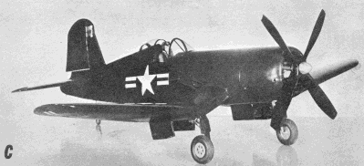
Later he promises the scale Corsair for Fox 59 with motor-speed (photo C). Model has
retractable landing gear, including tail-wheel, controllable rudder offset, droppable
carrier-hook-all operating through one handle.
|