|
Today, computer software has
replaced much of the simulation and experimentation that used to be the sole domain
of wind and smoke tunnels. The mathematical equations are so complex for high resolution,
3-dimensional calculations that very powerful computers are required to run even
relatively simple simulations. While there are programs that can be purchased for
about $1,000 that do a good job for uncomplicated shapes, large, university and
corporation scale computers are needed for "serious" work like designing commercial
and military aircraft, passenger cars, competition sailboats, and many other applications.
Even so, NASA, the ESA, and other large organizations still operate tunnels for
testing prototypes that have emerged from simulations. This article provides plans
and instructions for building your own smoke tunnel that uses components easily
obtained at the hardware store. If you have ever thought about building such a device
but haven't found an easy way to do it, this might be just what you've been looking
for.
A Wind Tunnel You Can Make and Operate
Okay, so be technical and label it a "smoke" tunnel. But that won't lessen the
value of your findings one bit!
By Paul J. Palanek
 This is an instrument of scientific proportions,
not just a novelty. The serious minded experimenter can probe many secrets relative
to the movement of air and bodies placed in its stream. Knowledge reaped from smoke
tunnel studies can lead the model builder, particularly the free flight enthusiast,
to design better models.
Prior to settling down to the serious task of building the instrument, let's
delve into a brief history of the wind tunnel - a close cousin to the smoke tunnel.
The world's first wind tunnel was built at Greenwich, England in 1871. Its designer,
F. H. Wenham, proposed it to the then recently organized Aeronautical Society of
Great Britain, as an instrument to obtain data on which a true science of Aeronautics
could be founded.
In 1901 Wilbur and Orville Wright built a small wind tunnel at Dayton and with
it tested some 100 different wing models at various angles of attack. In the year
of the Wrights' flight, Crocco built a wind tunnel near Rome; Prandtl built a large
one at Gottingen in 1908. Eiffel built one of unique design with an air tight testing
chamber at Paris in 1909. The British government constructed its first large tunnel
at the National Physical Laboratories in London, in 1910.
There are today about 200 tunnels in these United States. Half are for subsonic
work, both commercial and in schools; the remainder for testing at high speed. They
vary from low speed, low density types to tubes, developing 18,000 mph speeds by
hot expanding gases - in reality an explosion.
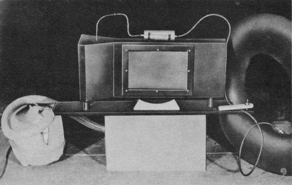
One of the most simple approaches to a "do-it-yourself" tunnel
we've ever encountered. This makes a terrific project for a science class, model
club, or a school science exposition entrant.
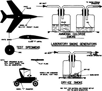
Smoke system and specimen details
There are two basic types. The first, called the open circuit (or "Eiffel" or
NPL) tunnel, has no guided return of the air. After the air leaves the diffuser,
it circulates by devious paths back to the intake. If the tunnel draws its air directly
from the atmosphere, entirely fresh air is used.
The second type, called a closed circuit, "Prandtl," "Gottingen," or "return
flow" tunnel, has, as the name implies, a continuous path for the air.
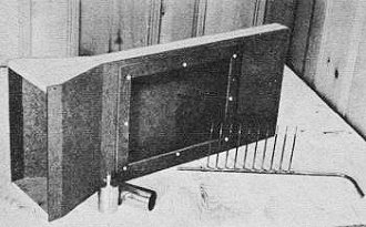
Our unit is a two dimensional smoke tunnel devoted exclusively to section testing.
For this type of airfoil research the test specimen is a flat cross section that
spans the shorter axis from one wall to the other. The tunnel is constructed of
common materials; what must be purchased, can be had for a few cents. A good deal
of the material came from the scrap, heap and waste bin. The most expensive component
was the lucite observation window. Glass could have been substituted, but would
have been more difficult to handle and fit.
Since copper tubing smoke manifold appears most difficult part, let's get along
with this. A piece of 1/4" or 3/8" diameter copper tubing is used. Drill eleven
holes enabling a press fit for the 1/8 " manifold reducers. Solder these tubes in
parallel. Be certain that the solder remains clear of the I.D. of the tubes. Exit
nozzles are soldered to the 1/8" reducers
Tunnel uses 1/2" bass or pine top and bottom, with 3/16" tempered Masonite for
the walls. Layout the contour lines and shape accordingly. Make the window cut-out
cleanly since it carries the sealing Lucite window.
Assemble tunnel by first inserting the smoke manifold, then with brads secure
the sides to the upper and lower walls. Seal off the exit end of the tunnel with
a piece of 1/2" hardwood. A wood baffle spans the minor axis of the tunnel; fasten
with brads in the shape of a "V" as indicated. This baffle prevents the smoke streams
from terminating sharply.
At this point, seal all seams with model cement. This will strengthen the assembly
noticeably, When the cement has dried, spray the tunnel both inside and out a dull
black.
Mount the tunnel on its three 1" diameter dowel legs fastened to the baseboard.
This will hold the instrument in good position for working. Note the location of
the securing bolts. With the tunnel positioned, secure the flanged pivot bushing
in the center of the vertical axis and in the center of the front face cut-out.
Secure to the aft end of the tunnel a vacuum cleaner flange, one to fit the vacuum
cleaner used. Keep this as air tight as possible for obvious reasons. Cut from the
full size plans the calibrated scale and cement to the face of a 1/16" plywood panel,
then fasten to baseboard, locating so zero line is directly below center line of
the pivot bushing, Use 1/4" sq. hardwood strip to mount the dial plate properly.
You will note that the entry end of the tunnel has a grating 1" sq. something
like an egg crate separator. Build this of 1/16" smooth balsa sheet. When complete,
the unit should fit snugly in place. This grid work straightens the air as it is
drawn into the tunnel.

Here's the reason you don't see any supersonic balloons flying around these days!
|

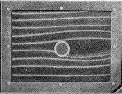
This should interest every model builder who notes air flow at the wing tips.
|

Now we're getting down to cases. Quickly, Henry, hand me the Clark "Y" section.
|
The smoke generator is a simple affair. It can be constructed from equal diameter
fruit cans or from machined brass rod. The wood cartridge carries five cavities
for five burning cigarettes. This assembly is fastened to snap-on clips for loading
and unloading.
Since a control of some sort is necessary to meter the air to the smoke generator,
a simple wood clamp is mounted to the rear of the unit on the baseboard. Rubber
tubing, 1/4" I.D. is used for all piping.
To pivot the test specimens, a brass or bronze flanged bushing is fastened to
the back face of the tunnel, fitting flush to the inside. The hole through the bushing
is of little importance - 1/8" to 3/16" diameter should do.
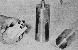
Cigarette smoke source.
Test specimens are outlined; these should be made accordingly of hardwood or
balsa. The pieces should be painted black with a narrow white border. This simplifies
photography if used. Tunnel is sprayed a dull black to provide good photographic
background.
Complete the face window. The Lucite fits snug into the tunnel opening with the
framing fastened to the window by #10 sheet metal screws. This assembly should fit
flush to the inside walls. It may be necessary (depending upon fit) to clamp the
window assembly in place to avoid any seepage of air.
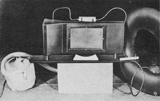
To create the decreased air pressure in the chamber, a vacuum cleaner of standard
make was used, along with an inner tube as shown in the pix to activate the smoke
flow.
We strongly suggest photography to permanently record each experiment. This pertinent
data can be referred to at a later date and further tests run with varied sequences.
The versatility of the instrument is up to the experimenter.
A large and fertile field of research almost totally neglected by the wind-tunnel
engineer is that covering non-aeronautical experiments.
Boats are seriously affected by drag and turn over angle. In a number of vessels,
the modern "decorations" on the stacks are the direct result of tunnel tests.
As road speeds have increased, more and more attention has been given to streamlining
of automobiles. Race cars, particularly those designed for attempts at the world
speed records, must of necessity pay much attention to wind tunnel tests.
A vast field also exists for commercial tunnel work such as air conditioning
outlets, rail-shielded inlets, automobile manifolds, drying setups, anemometer calibrations,
wind-driven power plants, and a host of air flow devices.
The editor will welcome comments on this tunnel-building feature. If you find
it of special interest, why not drop him a note. It would be very' much appreciated
if photos of completed smoke tunnels - especially in operation - were sent along,
too, to "American Modeler."
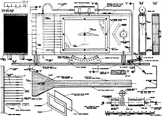
Wind Tunnel Plans
Bill of Material
1 pc. 3/16" x 12" x 12" Masonite for window frame; (2) 3/16" x 12" x %4" Masonite
for walls; (1) 1/2" x 4" x 8'0" white pine for top and bottom, pedestal base, deflector,
tunnel end; (1) 1" dia. x 12" dowel for pedestal risers; (4) 1/16" x 1" x 36" balsa
sheet for inlet mesh; 1 box 1" long brads to assemble tunnel; (1) pc. 1/4" O.D.
x 14" brass tubing for smoke manifold; (1) 1/8" O.D. x 36" brass tubing for manifold
reducer; (1) 1/16" O.D. x 36" brass tubing for exit nozzles; (1) 1/4" dia. rubber
tubing for smoke and air couplings; (1) flange, standard vacuum cleaner coupling
for Aft end of tunnel Air coupling; (2) metal fruit cans for smoke generator; (1)
1/16" x 2" x 2" sheet brass for manifold reinforcement; (3) 1/4"-20 x 4" nuts and
bolts for pedestal mounting; 1 can rubber cement for tunnel sealer; 1 can Krylon
black spray for tunnel blackener; 1 pc. 3/16" Lucite x 10" x 13" for specimen window;
1 doz. 10-32 bolts 3/8" long for window fasteners; 1 pc. 1/16" x 3" x 10" plywood
for angular setting; 1 pc. 1/8" dia. x 12" steel rod for segment pointer. Misc.:
Cement; solder and paste; white cardboard; small brads; inner tube for smoke generator
air blast.
Alternate Smoke Generating Devices for Classroom Demonstrations
Type A: Ammonia Chloride Smoke
Material needed: 2 wide mouth bottles; 2 large two-hole stoppers to fit; glass
tubing; ammonia hydroxide; hydrochloric acid; notes on setting up:
The apparatus may be set-up as indicated in the drawings. Air from a compressor,
a hand pump. or an old inner tube previously filled at a service station is most
satisfactory. If the smoke is not dense enough, try the use of a more concentrated
solution. Too concentrated solutions, however. are likely to produce particles that
will clog the tubes.
By the use of "T" or "Y" tubes three or four jets may be used at the outlet to
give smoke over a wider area. All experiments should be supervised by a trained
leader.
Type B: Dry-Ice Smoke
Material needed: 1 wide mouth bottle; 1 large Two-hole stopper to fit; glass
tubing; Dry Ice.
Dry ice may be obtained from such sources as dairies, ice cream factories, air
products companies, and drug stores. It costs a few cents per pound. One pound will
produce a good deal of "smoke." It must be used within a few hours.
Warm water will change the "Ice" into vapor more quickly and produce a denser
"smoke" than using cold water.
Notes: Suggestions for "Smoke Producers"
When used with a wind tunnel or in another air stream the smoke producers will
have to be placed so that the smoke will be carried along by the air stream. The
rate of production will have to be adjusted to the velocity of the particular air
stream (see text for detail. about metering damp). If the velocity is high, the
smoke may be too "thin" and thus not visible to the eye or a photographic plate.
The air velocity is from 2 to 10 mph depending upon the vacuum used. This can
be varied at the exhaust end of the vacuum cleaner.
Full-size construction plans for smoke tunnel are on Plan #457 by Hobby Helpers,
770 Hunts Point Ave., New York 59, N. Y. (50c).
|