|
Here is unique and sophisticated
1/2-A free flight model designed for and flown successfully in Half-A payload, Half-A
free flight, Class A free-flight, and it meets FAI gas requirements. By adding a set
of floats it can be flown in R.O.W. events. Chula Vistan's elliptical dihedral and use
of a diesel engine set it apart from many similar models of the era (mid-1950s). As with
many F/F models, the Chula Vistan's framework is a work of art that is most appropriately
covered in a translucent or transparent scheme with colored trim so that its structure
can be appreciated. Not being a free flighter, I do not know if it meets modern specifications
for current AMA or FAI events.
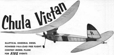
Chula Vistan PAA-Load Free Flight
Elliptical Dihedral Diesel Powered PAA-Load Free Flight Contest Model Plane for Five
Events
By CPO Tom Henebry
 This is the second of a series of small gas models
with an elliptical dihedral wing form. It is unique for a payload model in that it retains
the high performance of a true pylon, yet the simple cabin enclosure meets PAA's Half-A
payload specifications. It has been flown in Half-A payload, Half-A free flight, Class
A free-flight, and it meets F.A.I. gas requirements. By adding a set of floats it can
be flown in R.O.W. events. All told, five events may be entered with this one basic model.
The dummy is located exactly on the C.G., and flying with or without the dummy doesn't
noticeably change the flight pattern. This is the second of a series of small gas models
with an elliptical dihedral wing form. It is unique for a payload model in that it retains
the high performance of a true pylon, yet the simple cabin enclosure meets PAA's Half-A
payload specifications. It has been flown in Half-A payload, Half-A free flight, Class
A free-flight, and it meets F.A.I. gas requirements. By adding a set of floats it can
be flown in R.O.W. events. All told, five events may be entered with this one basic model.
The dummy is located exactly on the C.G., and flying with or without the dummy doesn't
noticeably change the flight pattern.
Rather than repeat at length the construction of the wing jig, I refer you to page
37 of the January 1954 issue of Air Trails. The jig for Swayback and the Chula Vistan
are the same in type and construction, the only difference being in the curve line. By
comparison you can see the Chula Vistan is flatter in the center section and rises more
sharply at the tips.
Assuming
you have the jig, with the plan located properly in the concave form, install the inner
piece of 1/8" sq. balsa that forms the leading edge. Outline it with pins and weight
it down so it stays in contact with the form along its entire length. Cement the leading
piece of 1/8" sq. along its entire length to the piece already installed; you now have
a leading edge 1/8" high and 1/4" wide. Repeat these steps until you have the leading
edge built up to 1/4" sq. and evenly cemented together at all points of contact. The
trailing edge is made in the same manner except the inner piece of 1/8" sq. is installed
a little later.
When the leading and trailing edges are set up, cement the slotted 1/8" sheet tips
in place. Follow with the 1/8" x 1/32" bottom cap strips, cut to size and cement the
1/32" x 2" cross-grained sheet in the indicated position in the center section. After
the cap strips and center section strips are in place, cement the inner piece of 1/8"
sq. trailing edge to the trailing edge as well as to the tops of the cap strips and center
section piece.
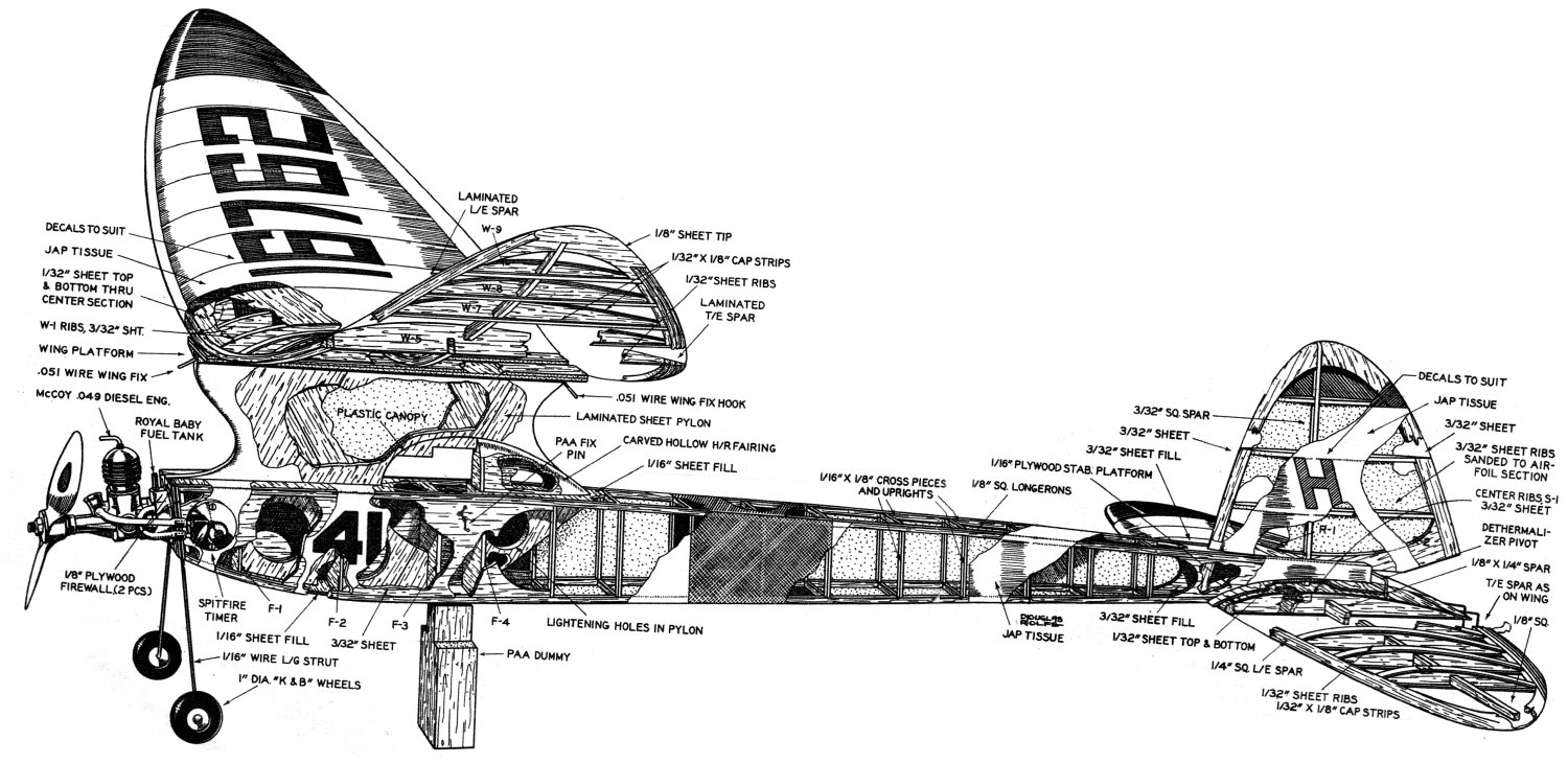
 Detailed cutaway drawing is by Douglas Rolfe,
nationally known aircraft artist. Mr. Rolfe's work appears regularly in this publication
and in the forthcoming "Air Progress" Detailed cutaway drawing is by Douglas Rolfe,
nationally known aircraft artist. Mr. Rolfe's work appears regularly in this publication
and in the forthcoming "Air Progress"
Cement a piece of tough 1/8" sq. from tip to tip, filling the slots in the tips and
cement securely to all cap strips and center section strip. You will need to weight the
spar down with any small heavy object at hand to assure even contact with all cap strips.
The spar is built up by cementing successive pieces of 1/16" x 1/8" to the 1/8" sq. already
installed. These pieces are progressively shorter as indicated, so when the spar is complete
it is not unlike an automobile leaf spring, thicker in the center and thinner at the
tips.
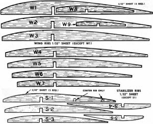
To complete the wing, cement in the ribs and the top cap strips, cover the three center
section ribs with cross-grained 1/32" sheet and finally add the unslotted pair of wingtips
on top of the installed pair. When the wing is thoroughly dry remove it from the jig,
shape the leading and trailing edges and the tips with sandpaper - and of course an overall
sanding with fine sandpaper. The wing is now ready to cover. I believe it is at this
point that the builder realizes the beauty of this type of wing construction. No weak
dihedral joints, no chance of misalignment, and even without covering its resistance
to torsion is amazing. The secret here of course is that every strength member in the
structure is pre-stressed.
Stab construction is the same as the wing except the leading edge and the spar are
not laminated. The spar should be tapered as indicated before installation.
 Fuselage construction is conventional; make the
two sides over your full-sized penciled plan. You will note that the longerons are 1/8"
square but the sheet fill-in is 3/32"; this is intentional. Place scrap pieces of 1/32"
sheet under the sheet parts to bring them flush with the longerons on the first fuselage
side. Make the other side directly over the first, but push the sheet parts down so they
are 1/32" below the edge of the longerons. On assembly be sure the depressed sheets are
on the outside; the longerons are then sanded smooth with the face of the sheet before
covering. Fuselage construction is conventional; make the
two sides over your full-sized penciled plan. You will note that the longerons are 1/8"
square but the sheet fill-in is 3/32"; this is intentional. Place scrap pieces of 1/32"
sheet under the sheet parts to bring them flush with the longerons on the first fuselage
side. Make the other side directly over the first, but push the sheet parts down so they
are 1/32" below the edge of the longerons. On assembly be sure the depressed sheets are
on the outside; the longerons are then sanded smooth with the face of the sheet before
covering.
The pylon is made from laminated pieces of 3/32" x 3" overlapping each other at 60
degrees. The pylon extends through the fuselage to the broken line on the drawing. After
laminating the pylon is cut to shape, sanded, and lightening holes cut where indicated,
and formers F-1, 2, 3 and 4 are cemented in position on the pylon. The complete firewall
assembly containing the landing gear and engine mounting nuts is cemented in place securely.
Insert a waxed PAA dummy in position between F-3 and F-4 - be certain he fits snugly.
With the dummy in place, cement the fuselage sides to the formers and firewall, being
careful to maintain correct alignment. Cement the 1/16" x 8" cross pieces in place, then
the completed rudder, fill in as indicated with 1/16" sheet. The 1/16" plywood stab platform
is cemented in place with the fuselage lying on a smooth, flat surface and the stab in
place. Be sure it follows the curve of the stab exactly and that the stab is in line
with the fuselage bottom.
The headrest fairing is carved from soft balsa, hollowed out and installed as shown.
The plastic canopy is cut to size, slotted to fit around the portion of the pylon that
protrudes through it, and cemented in place. Cut the required holes for the engine timer
but do not install it until after covering. Finish shaping the pylon and add the 3/4"
trailing edge stock plus the two layers of 1/16" sheet, leaving a 1/8" wide strip on
the center line for a wing key.
 The completed structure is covered with Jap tissue,
water sprayed and given four coats of butyrate dope. It is a good idea to double-cover
the stab bottom; because of its low position it is prone to minor tears and damage. After
covering install the engine timer, wing hold-down wires and the bent pin hooks that retain
the payload dummy. Cement a piece of hard 1/16" x 1/8" on the centerline of the bottom
of the wing. Before the cement dries, secure wing in place and check the distance from
each tip to the top of the rudder - be sure they are equal. The completed structure is covered with Jap tissue,
water sprayed and given four coats of butyrate dope. It is a good idea to double-cover
the stab bottom; because of its low position it is prone to minor tears and damage. After
covering install the engine timer, wing hold-down wires and the bent pin hooks that retain
the payload dummy. Cement a piece of hard 1/16" x 1/8" on the centerline of the bottom
of the wing. Before the cement dries, secure wing in place and check the distance from
each tip to the top of the rudder - be sure they are equal.
The wire pivot bar and dethermalizer parts are formed and cemented in place. Cement
liberally and use strips of Band-Aid backing (crinoline) to further reinforce the points
of contact between the wire and the structure. Do not force the wire into the wood but
drill holes for it, which results in a stronger joint.
The McCoy Diesel shown gave me the best Half-A and Payload results, but any other
good Half-A engine could be used. The Royal Baby Spitfire tank shown needs only minor
alterations to fit the McCoy. Filing off a small flange, a home-made gasket and drilling
the tank mounting holes slightly oversize will make it work. If you care to compete in
Class A events, a Cub .074 or a Royal Spitfire can be attached to the firewall with wood
screws.
You may note that there are no provisions On the drawing for any form of glide turn
control. You may use your own favorite method, a tilted stab, a floating tab on the left
wing or maybe you prefer, like me, to use 1/16" to1/8" wash-in on the right wing. I feel
this prevents the right wing from "digging in" in a tight power turn. Whichever method
you prefer, the model is trimmed to glide smoothly to the left before power is applied.
Start the power flights on low power settings and gradually approach maximum power, making
minor thrust line corrections until a smooth, fast, right climbing turn and a floating
left glide result. Remember the C. G. position is right at the dummy - if you shift engines,
be sure the model balances at the same spot.
Notice:
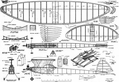
The AMA Plans Service offers a
full-size version of many of the plans show here at a very reasonable cost. They
will scale the plans any size for you. It is always best to buy printed plans because
my scanner versions often have distortions that can cause parts to fit poorly. Purchasing
plans also help to support the operation of the
Academy of Model Aeronautics - the #1
advocate for model aviation throughout the world. If the AMA no longer has this
plan on file, I will be glad to send you my higher resolution version.
Try my Scale Calculator for
Model Airplane Plans.
Posted April 5, 2014
|