|
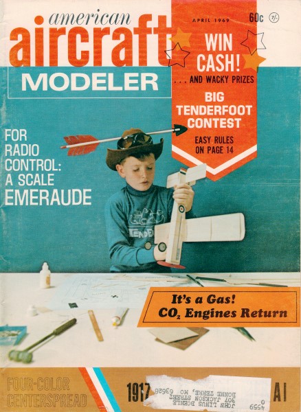
Here is the article and plans for the Piel Emeraude that I electronically
scanned from my purchased copy of the April 1969 American Aircraft Modeler
magazine. Because they span two or more pages, I had to adjust the size
and alignment a bit to get halves to line up properly. You might be able
to scale up the image below. Plans for this fine model were drawn by Mr.
Bob Morse. All copyrights (if any) are hereby acknowledged.
"The Piel CP-30 Emeraude is an aircraft designed in France in the mid-1950s
and widely built both by factories and homebuilders. It is a low-wing cantilever
monoplane with fixed tailwheel undercarriage and side-by-side seating for
two. The prototype was designed and built by Claude Piel."
- Wikipedia
Piel Emeraude Article & Plans
 The May, 1964, issue of Experimental Aircraft Association's Sport Aviation
magazine carried an article describing the Emeraude, designed by Claude
Piel of France and built by Wayne Barton of Rush, N. Y. The May, 1964, issue of Experimental Aircraft Association's Sport Aviation
magazine carried an article describing the Emeraude, designed by Claude
Piel of France and built by Wayne Barton of Rush, N. Y.
Popular French-designed home-built makes an ideal R/C ship capable of
AMA pattern maneuvers, including snap-rolls and inverted spins.
BOB MORSE as told to Leon "Duke'" Crow
After seeing the photos of, this beautiful home-built aircraft, we had
to duplicate Mr. Barton's marvelous ship for R/C. We obtained from Falconair
Aircraft Co. of Edmonton, Alberta, Canada, a descriptive brochure and three-view
drawings.
The Emeraude is quite an airplane, having a wing span of 26 ft. 4 in.,
length of 21 ft., and a wing area of only 117 sq. ft. It can tote two adults
at a maximum speed of 112 mph, or cruise at 103 mph on only 65 hp. Increasing
the power to 105 hp jumps the cruise speed to 120 mph and maximum speed
increases to 137 mph.
The cost of building a ship at home can be difficult to nail down. Mr.
Barton man-aged to build his Emeraude, using all new materials except for
instruments, wheels and a majored engine, for only $1,223. This is really
a lot of airplane for the money! We plan, someday, to begin construction
of our own Emeraude, but until then, we will have to enjoy our model.
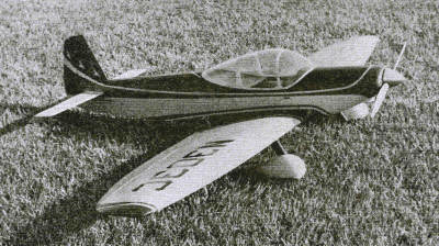
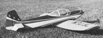
The real plane also is an exciting aircraft. Clean
lines give fast cruise performance. Large wing area permits slow
easy landing. Model's airfoil also permits aerobatics.
Since building the ship in 1964, we have enjoyed many many flights. It
is an excel-lent flyer, very stable and will perform the complete '68 AMA
pattern (including snap rolls and inverted spins) maneuvers. And you wouldn't
believe the ground handling; takeoffs and landing have to be seen to be
believed with these old-fashioned bicycle landing gears.
Wings: Construction is straight-forward and should present no
problem. While the wing appears difficult to build because of its
elliptical shape, it is, in reality, a straight wing with only the
outboard portion, incorporating
the ailerons, being elliptical. We chose the full-depth spar with inter-locking
ribs as the most practical method of obtaining the elliptical wing shape
and to provide the, correct spar profile in the outboard section of the
wing.
Begin construction of the wing by pinning the inboard trailing edge
Sheet to the flat building board. The main spar with the ribs keyed loosely
in place is then placed on 3/8" square spacer blocks (you'll see the reason
for this when you pin the ribs down to the bottom trailing edge sheet).
With the loose assembly in place, key the outboard ribs in place and then
position the aileron spar so that all ribs are in line. With this spar pinned
and blocked in place, the ribs can be disassembled and, reassembled with
glue. After the glue has taken its permanent set, the leading edge, nose
sheeting and trailing edge sheeting can be installed. Add the rib cap strips
and, when the assembly has cured, lift the panel and add the landing gear
blocks, lower nose sheeting, and lower cap strips.
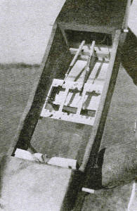
Looking through wing opening and out the canopy from the inside. There's
plenty of room for three large servos side-by-side.

Inverted engine easiest to start. Don't prime into cylinder; just wet
side of piston with fuel just before flipping prop.
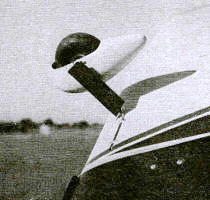
Wheel pants.
Repeat this for the opposite panel and you are ready for wing joining.
Sand the skin sheeting at the roots to the dihedral angle shown and butt
glue the two panels together. Take all the time you need at this point and
make absolutely sure that the two panels are perfectly mated. If you do
this right, you will have a wonderful flyer. Do it wrong and you'll have
a dog! Assuming you have done it right and your glue has set, paint a 2"-wide
strip of resin around the center-section joint, press a strip of glass cloth
into the resin, and finish off your basic wing structure with a final coat
of resin over the cloth.
The ailerons are built now and can be either built-up as shown, or hogged
out of soft 3/4" sheet stock.
Fuselage: It is rather straight-forward and should present no problems.
Start by making two complete side assemblies; don't forget, one right-hand
and one left-hand. These consist of the 3/32" side sheets, the ply wing
opening doubler, the vertical 1/8" x 3/8" stiffeners and the stringers.
After these have been finished, gently crack the 3/32" sheet at the forward
edge of the ply doubler as shown in the top view; this will make things
a little easier later on. Assemble the fuselage upside down on the building
board with the front hanging over the edge of the board so that the firewall
and the fuel tank bulkhead can be installed. Add the gusset blocks and engine
mount beams, then add 1/8" x 3/8" cross pieces at the uprights and top of
sides, then the 3/32" bottom sheeting.
Pick up the fuselage now and complete the rounded, stringered top. To
get straight stringers, pre-notch only the aft cabin former and install
the other three turtle deck formers without the notches. Position each stringer
as shown and mark the position on the rest of the formers, then cut in
the notches and install each stringer as you go along.
Miscellaneous: As the model is built to 1/5 the size of the real ship,
there is room for almost any type of radio gear. If you would like to operate
the wing flaps, there is plenty of room for the control installation.
Conventional torsion-bar landing gear used wheel pants from Stafford
Chipmunk kit with strut faired by balsa and silk wrapping. There are two
pretty hard nuts to crack in building this bird, and we will tackle the
tough one first. The cockpit canopy resembles a rather small birdbath!
There are two ways of getting a canopy on your ship: 1) carve a hard balsa
pattern 1/16" under-size from the drawing contours and finish it glass-smooth
with Hobbypoxy, or a similar hard coat, and then heat. 1/8" Acrylic or Polyvinyl
sheet to a pliable state and quickly press over pattern. The second
problem is wheel pants. We did it the hard way - made molds and laid up
our own with resin and cloth. Our next ship will have Jack Staffords' fiber-glass
Chipmunk or the Williams Bros. plastic parts.
As far as power is concerned, the ship is an excellent performer with
a 45 mill up front, but for competition flying, a 60-size engine will really
put those rolls "on a wire." Our ship is silk covered and finished in butyrate
color in the same scheme as Mr. Barton's N9441H.
Every construction article we've read has cautioned the new builder to
check things out before you go down to your favorite 5,000-ft. runway. We're
no exception. Almost is not good enough. It's got to be right. Check out
your control system. Recommended ground range, control linkages free, vibration
checks with engine running, and so on. If anything doesn't look quite right,
fix it now, or you won't have anything to fix later. Flying: An experienced
flyer will have no trouble with the Emeraude. One word of caution to our
hot-dog tricycle-geared pilots, take it easy on the throttle on take-offs.
Ease her up to about half throttle and watch the tail lift off. When she's
got some speed and the controls---become effective, you can firewall the
throttle and really go!
We have flown the trike-geared ships for a long time now, but two-wheel
lift off and touchdowns of a bicycle gear really give you a thrill.
For the new R/C flyer, Emeraude is a gentle, forgiving ship, and with
an experienced flyer as a copilot, she makes an excellent trainer.
If you would like to get into the scale competitions, here's your chance
to grab a few points with a relatively easy-to-build dependable flyer.
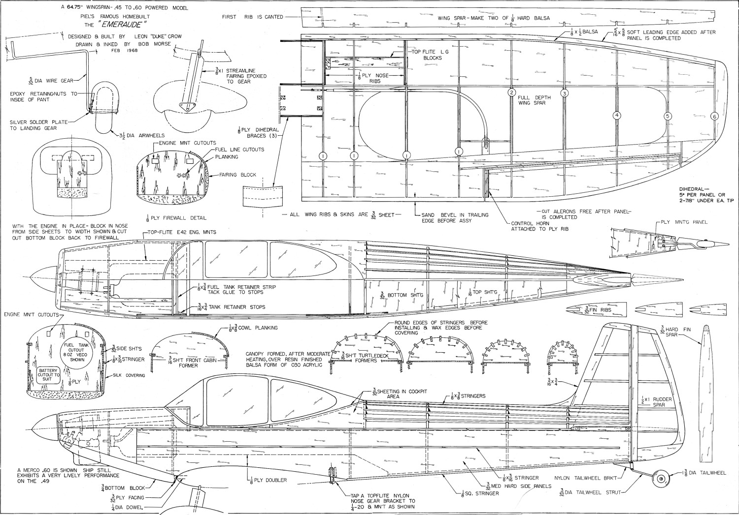
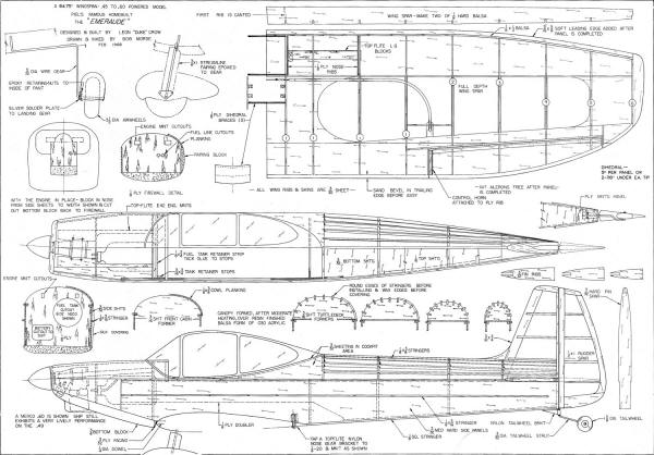 Piel Emeraude Plans Sheet 1
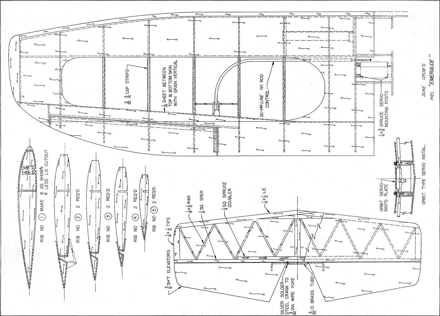
 Piel Emeraude Plans Sheet 2\
 Piel Emeraude 3-View
Notice:
The AMA Plans Service offers a
full-size version of many of the plans show here at a very reasonable cost. They
will scale the plans any size for you. It is always best to buy printed plans because
my scanner versions often have distortions that can cause parts to fit poorly. Purchasing
plans also help to support the operation of the
Academy of Model Aeronautics - the #1
advocate for model aviation throughout the world. If the AMA no longer has this
plan on file, I will be glad to send you my higher resolution version.
Try my Scale Calculator for
Model Airplane Plans.
|