|
The only sound that is sweeter than
two model airplane engines slowly droning in and out of sync is three - or even four
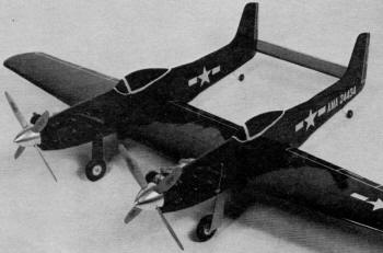
- engines droning in and out of sync. This profile F-82 Mustang control line model by
Terry D. Aldrich uses twin 35 size engines with solid balsa profile fuselages and a simple
built-up wing. Its 52½" wingspan and 10" cord makes for a fairly large model,
but with a pair of 35s up front it should be quite a performer. Adaptation to electric
power would be a fairly straight-forward process, but it just wouldn't have anywhere
near the awesomeness without the engines screaming.
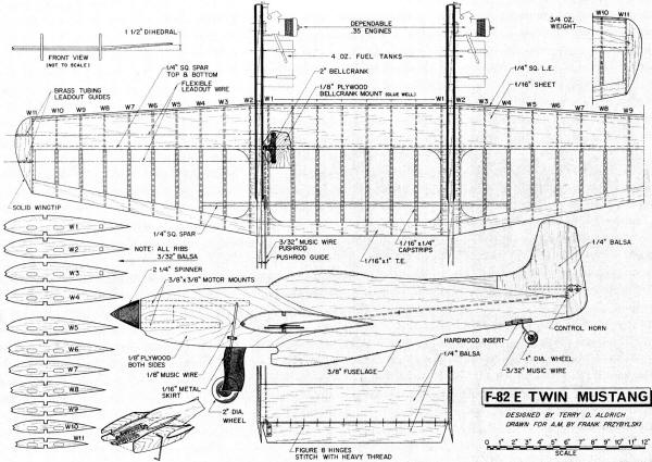
F-82 Twin Mustang
A control-line show-stopper, this profile F-82 is as startling in appearance as the
real one. It's easy to build, too!
|
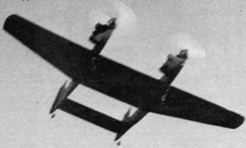
In flight, with its two 35s snarling, the Twin Mustang has maximum
appeal. Clubs take note. It is an ideal demonstration model.
Four-bladed props are a plus. To construct - cement two regular wood
props together, using a half-lap joint and epoxy. Carefully check the balance and true
running of the prop tips. Wing is the only built-up component; the others are constructed
of sheet stock.
|
Built by North American Aviation Inc., and designed as a long-range, high-performance
fighter-bomber, this twin-engine, twin-fuselage aircraft was test flown July 6, 1945.
Our model is a profile, scaled one inch to the foot, giving a wingspan of 52.5". Two
35 McCoy powerplants provide more than enough get up and go to give all the thrills one
could want in an aircraft.
Used as a show plane, it is a crowd pleaser of the first order. Painted all black
with white trim and rubbed out to a high polish, this plane becomes something one enjoys
having.
The airfoil shown was used because of the anticipated weight of this type of model.
For those who want more than level flight and loops, a symmetrical airfoil may be substituted.
Fuselage: Use hard-grade balsa 6 x 36 x 1/2 stock for the fuselage.
Cockpit and air scoop are butt glued from scrap (if cockpit and air scoop included use
7 1/4 x 36 x 1/2 stock). The fuselage is tapered from rear of cockpit to rudder, per
the drawing. The 1/8 hard-grade plywood doublers extend from the nose to halfway past
the wing leading edge.
Motor mount material is 1/2 x 3/4 x 6, hardwood. Distance between the mount bearers
depends on the motor used and crankcase size. The 2 1/4 spinner is a Veco product.
The 35 powerplants are mounted with the cylinders to the outside of circle. Drill
1/8 holes and use 4-40 lock nuts and bolts. (Blind nuts may be substituted.) On some
engines the needle valves will need to be in the top position, for ease of making adjustments.
Side mount 4-oz. tanks, using strap-type hold-downs. Fuel filters are an extra safeguard
for reliable and smooth running.
Make left and right 1/8 landing gear struts for 2" wheels (Perfect or Veco). Also,
bend left and right tail wheel struts, using 1/16 wire set in hardwood. The hardwood
is recessed into the fuselage. Make two metal main-gear skirts. Attach them with nylon
clamps.
The vertical tails are 7 1/2" high. Use 3/16 thick balsa, rounded as shown. The rudder
is tapered and offset to outside of circle to maintain line tension.
The horizontal stabilizer is 3 x 14 11/16 x 1/4 balsa. Elevator is 1 1/2 x 14 1/2
x 1/4, tapered. Note that the horizontal stabilizer is countersunk into the vertical
stabilizer 3/32 for extra strength. Distance between one vertical stabilizer and the
other vertical stabilizer is 14.5". Make figure-eight elevator hinges from waxed string.
Wing: The center section rib length is 10". A standard lifting airfoil
is used. A symmetrical, stunt airfoil may be substituted for the full pattern. Cap strip
the ribs with 1/4 x 1/16 balsa. The 1/4 x 1/4 main spars are located 3 1/2" from the
leading edge, the single rear spar 2 3/8 from trailing edge. Use hard 1/4" sq. balsa
for the leading edge. The wing's 1/16 sheeting butts against the leading edge and continues
rearward, overlapping each main spar. Use medium to medium-hard sheeting on the wing.
Top and bottom trailing edge is 1 x 3/32. Incorporate 1 1/2 dihedral at each wing tip.
Add 1 1/2-2 oz. of lead weight to outboard wing, buried in the solid wing tip.
Bellcrank is a standard 2" heavy-duty type. Note that it is set in reverse. This places
the pushrod (3/32) next to the left fuselage. The plywood bellcrank mount is epoxied
to the bottom main spar, and butted to left fuselage center wing rib. Locate a guide
eyelet halfway to elevator to prevent bowing of pushrod. Lead-out lines are swept back
slightly, as normal on all U-control models.
Use plenty of balsa filler on all solid balsa components before the final assembly.
Silk the wing and apply a filler coat over the silk before final assembly. Check all
parts for a correct fit and alignment. Use a slow-drying epoxy on all final joints for
strength. For extra strength, make epoxy fillets at wing roots and tail roots.
Finish: The grade of finish depends upon the builder. The finish
I used is as follows: three filler coats, full strength, and a lot of sanding between
each coat for all the pre-assembled parts. Wing is then silked and six coats of dope
applied with sanding between each coat. At this time, apply three more coats to the fuselage
and tail assembly. Total overall, is six coats. The model then is assembled. Spray on
a coat of black (finish color) five times, applying three coats at each spraying - total
of 15 color coats. Let the finish dry several days between these spray sessions. Also
lightly sand with 350 grit sandpaper before each session. Rub out and wax for the final
high polish.
F-82 Twin Mustang Plans
Notice:
The AMA Plans Service offers a
full-size version of many of the plans show here at a very reasonable cost. They
will scale the plans any size for you. It is always best to buy printed plans because
my scanner versions often have distortions that can cause parts to fit poorly. Purchasing
plans also help to support the operation of the
Academy of Model Aeronautics - the #1
advocate for model aviation throughout the world. If the AMA no longer has this
plan on file, I will be glad to send you my higher resolution version.
Try my Scale Calculator for
Model Airplane Plans.
Posted June 14, 2014
|