|
Website visitor Ken E. requested the Flying
Funtique article from the April 1969 edition of American Aircraft Modeler. The Flying Funtique
is a rubber-powered free flight model that is part of AAM's "For the Tenderfoot" series that presented
easy to build airplanes with full-size plans printed with the articles. A unique feature of the Flying
Funtique is that the designer, William Hannan, provided patterns for finishing the model in five different
liveries.
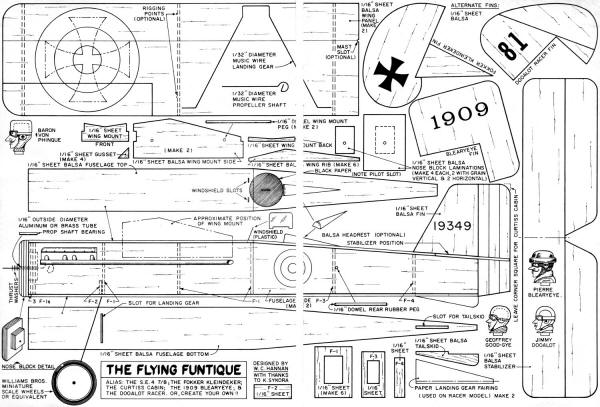
Flying Funtique
 For the Tenderfoot
By William Hannan
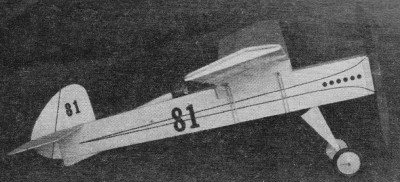
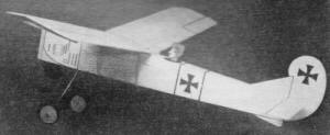
Here's a simple-to-build model that may be finished in any manner of your choice. If you like antique
"aeroplanes," you can decorate your model to resemble one of the famous vintage channel-crossers. If
World War I holds your interest, your Funtique can be finished to look like either an Allied or German
machine. Perhaps classic airplanes of the 20s or 30s are your dish .. then try the Curtiss Cabin, the
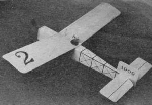
1909 Blearyeye, or maybe the sporty little Dooalot Racer.
 Actually, the model may be converted from one style to another
after it is finished, but it is suggested that you pick out one type at the beginning and stick with
it. You can follow one of the examples shown in our photos, or let your imagination go to work and come
up with your own design. How about a Sopwith Plop? Or maybe an Oldport 17? Or a Clodrun Racer? Actually, the model may be converted from one style to another
after it is finished, but it is suggested that you pick out one type at the beginning and stick with
it. You can follow one of the examples shown in our photos, or let your imagination go to work and come
up with your own design. How about a Sopwith Plop? Or maybe an Oldport 17? Or a Clodrun Racer?
This model is constructed almost entirely from 1/16" sheet balsa. Use care in selecting good wood,
and you will have a much better performing aircraft than one built out of "any old wood." When you are
choosing balsa, look for nice light white stock, and sight down each piece to be certain that it is
not twisted or warped.
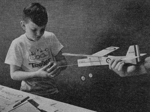
 Study the plans and photos before you start building. This will
enable you to understand the way the various parts fit together. By reading the step-by-step directions
and checking with the pictures, you should be able to construct the model easily. If you do run into
a problem, ask another modeler or an older person for help. You may even be able to talk them into building
a Funtique of their own! Study the plans and photos before you start building. This will
enable you to understand the way the various parts fit together. By reading the step-by-step directions
and checking with the pictures, you should be able to construct the model easily. If you do run into
a problem, ask another modeler or an older person for help. You may even be able to talk them into building
a Funtique of their own!
CONSTRUCTION
Fuselage: The fuselage or body is quite easy to build, and very strong. First, make
paper patterns of each part, including one top, one bottom, two sides, and the various bulkheads (formers),
which are identified on the plan as F-1, F-2, etc. Note that slots must be cut for the tail skid, landing
gear, windshield (if used) and pilot. Also make the small holes in the body sides for the rear rubber
peg.
Place the fuselage bottom flat on your workbench and glue on the bulkheads, which should be carefully
aligned both from the top and side view. Next, add one fuselage side, being careful that it lines up
exactly with the edge of the fuselage bottom. Install the remainder of the bulkheads, as shown in the
photos. The bulkhead closest to the nose is made of three layers glued together. This creates extra
strength where it is most needed. After all the bulkheads are installed, the second side may be added.
It may be helpful to pin or tape the side in place while the glue dries.
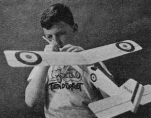 Use a stuffing stick (see article) to insert rubber motor
in the fuselage. Short dowel peg holds aft end of the loop of rubber.
 Stretch-winding allows more turns and longer flights. Stretch
motor 15-23"; start to wind. Move in as you pack in the turns.
Next, bend the wire landing gear to the shape shown on the plans. Notice that the landing gear is
bent forward at a slight angle, as may be seen on the side view. Insert the landing-gear wire between
the two bulkheads which are on either side of the landing-gear slot. Fill the slot with glue, both from
above and below the wire, and put aside to dry, preferably overnight. This glue joint must be strong,
or your landing gear will rip loose on the first hard landing. The top of the fuselage may now be added.
Sandpaper all four corners of the assembly until all edges are smooth. Insert and glue the tailskid
into its slot.
The nose block is made of laminations in the manner of the front bulkhead. When making these "plies,"
alternate the direction of the wood grain. One ply should have vertical grain, the next horizontal,
and so on. Stack the parts together and place a weight on top until dry. Be sure that the rear of the
nose block is a snug fit into the front bulkhead, or it will fall out when the rubber motor runs down.
The fit can be tightened if need be, by gluing a thin strip of paper along one side of the back portion
of the nose block.
After the nose block assembly is thoroughly dry, drill a hole in it for the propeller shaft bearing.
This bearing is made from a short length of metal tubing. Either aluminum or brass will work fine, but
aluminum is easier to cut. Roll the tubing back and forth under a sharp blade to score a groove around
it. Then snap it apart, and lightly sand the burr off the tube's end. Roughen up the outside of the
tubing with a file or sandpaper so that the glue will be able to get a grip on it. Glue the tubing into
the nose block, taking care that none of the glue runs inside the bearing hole. Next, glue on the paper
nose-block decoration of your choice.
The prop shaft is bent to shape, as shown on the plans, and inserted into the bearing in the nose
block. Add three or four washers to serve as thrust bearings. Place the propeller of your choice on
the shaft and be certain that it has enough clearance to revolve freely. With some propeller designs,
it may be necessary to add extra washers to obtain enough space between the prop blades and the nose
block. Most commercially produced propellers are slightly out of balance. To improve performance and
reduce vibration, sand the heaviest blade, until the prop will stay horizontal on its shaft, without
one blade falling to the bottom.
Obtain a pair of wheels about 1 1/8" to 1 1/2" diameter. We used a pair of Williams Brothers miniature
scale wheels since they help to give a vintage look to the model. With the Williams wheels, it will
be necessary to glue short sections of metal tubing into the hubs to reduce the hole size. This is easy,
because the same type tubing used for our prop shaft bearing can be used. To retain the wheels, you
can bend up the ends of the wire axles, or glue tight-fitting electrical insulation on the axle ends.
Stabilizer: This is cut out using the usual pattern system, and the edges sanded
and rounded slightly. This achieves three purposes: It streamlines the surface, reduces the weight,
and perhaps most important, creates a workmanlike appearance. A little sanding is often the main difference
between a so-so model and an outstanding one. Glue the stabilizer in place, being sure that the alignment
is correct, as seen from both the top and rear view.
Select the fin shape to suit your model, and cut and sand it to shape. Install it on the model, and
check that it is correctly located.
"Stuffing Stick"
 For inserting rubber motor (make from
1/8" square balsa)
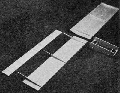
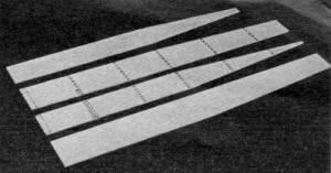
Wings: Each wing panel is made from one sheet of balsa 2" wide, one sheet of balsa
1" wide, and three wing ribs. Using tracing paper patterns, cut each part to shape and sand the edges
lightly to make them smooth. Place the wide portion of each wing panel on your work bench upside down,
and glue on each wing rib, being careful that they are in correct alignment. If the ribs do not seem
to stay in place, they may be held down with straight pins or masking tape while the glue dries. Next,
turn the panels over and fit the 1"-wide portions of the wings in place. If the rear edge is beveled
slightly with sandpaper, it will fit up against the 2"-wide sheet more snugly. Again, if the wood does
not want to stay in place while the glue dries, use pins or tape to hold it.
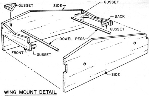
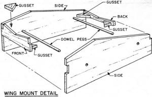 Wing Mount Detail
 With pencil or ball-point, mark location of all bulkheads
on the fuselage's parts.
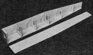 With fuselage bottom kept flat, glue bulkheads to it. Keep
them erect and aligned.
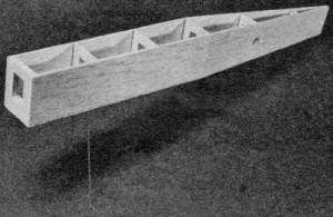 Install the landing-gear wire and glue securely. Then add
the top of the fuselage.
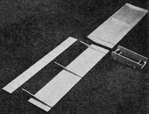 Two balsa sheets and three triangular ribs make up each
wing panel. Note wing mount.
Wing mount: The wing mount is made from a front piece, two side pieces, a rear piece,
and four gussets. The wing mount detail shows the relationship of these parts. Cut out each part using
paper templates as a guide. Be certain to follow the angles exactly, as they are important in making
your model fly properly. The parts may be glued together, being careful that this assembly does not
get twisted or out of line. Note that the gussets add strength to each corner joint. Next, the hardwood
dowels are inserted into their holes and glued in place.
The wing mount may next be glued to one of the wing panels. This will give the wing panel an upward
slant, or dihedral. When the joint is dry, place the other wing panel in position, but do not glue.
Note that the two halves do not fit quite together, because of the dihedral angle. A little trimming
and sanding will enable you to get a better fit. When you are satisfied with the joint, glue the second
wing panel in place, checking to see that it lines up well with the opposite member. Take your time
with this as the flight stability of your finished model will depend to a great degree on the alignment
of this unit.
When dry, the wing assembly can be placed on the fuselage, and secured with two common rubber bands.
Be careful when putting them on, because they can cause damage to the balsa wood, if stretched too tightly.
Decorations: Although the various makings are not really needed to make your model
fly, they add a lot of character that will make the airplane much more realistic and fun. The photos
should give you a pretty good idea how the model may be finished, but here are a few additional hints:
1909 Blearyeye: A small hole is drilled at the center of the wing, and a 1 1/2"-long
piece of hardwood dowel is glued in place to serve as a rigging mast. The actual rigging is sewing thread,
and may be sewed right through the wings at the rigging points shown on the plan. A drop of glue will
hold the rigging to the top of the mast.
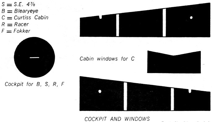
The black paper circle representing the cockpit is glued on the wing, as shown in our photos) as
is the paper pilot. The rear fuselage structure is represented with strips of thin black chart tape,
or you may draw the lines on with a marking pen. A ruler will make it much easier to put these lines
on straight. Chart tape can be purchased in several widths and colors at art supply stores, or some
hobby stores carry it under the name of striping tape. It is also used for slot cars. The competition
numbers may be cut from the magazine, or you may prefer to use different ones. A good source of large
numbers is an old wall calendar. The 3-cylinder radial engine drawing is cut from the magazine and glued
to the nose-block, which completes the model.
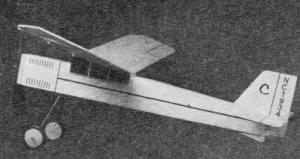
The Curtiss Cabin: The letter Cs and the NC numbers are cut from the magazine and
glued on the fin. The cabin windows are cut out and glued to the wing mount. If you wish, you can add
an exhaust stack on each side of the cowling. The two rows of louvers are made from short strips of
chart tape, as are the lines on the fuselage sides, aileron outlines, etc. Choose whichever radiator
drawing you prefer, and glue it on the nose block.
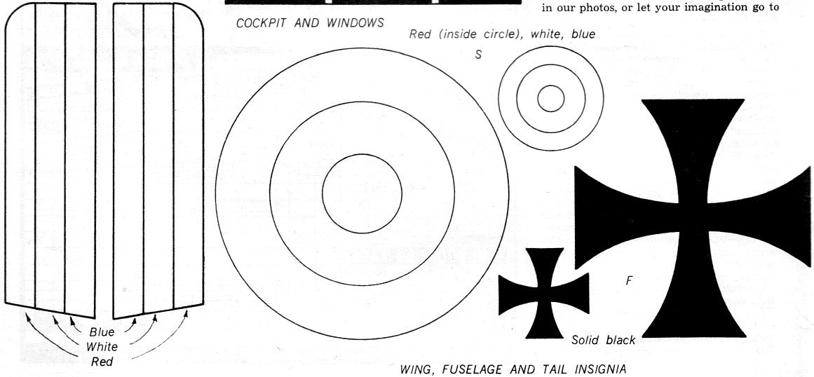
The Fokker Kleindeker: Cut out the various iron crosses and cowling sides and glue
them on the model. The black circle representing the cockpit is glued in the same location as shown
on the plans, and the mighty Baron von Phinque is inserted in his slot. Next, the radiator drawing is
glued to the nose block. If you wish to give your model an extra Fokker touch, you can make scallops
in the trailing edge of the wing. To do this, wrap a piece of sandpaper around something round, such
as a screwdriver handle, and carefully sand scallops at regular intervals into the wing.
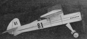
The Dooalot Racer: This little pylon polisher is a cinch to decorate, and looks
like it's roaring along even when standing still! The cockpit and pilot are located in the same place
as the Fokker model, but a headrest carved from scrap balsa is added. The racing numbers may be cut
from the magazine or an old wall calendar. The fuselage stripes, aileron separations, etc., are made
from chart tape. If you prefer, a solid teardrop of colored tissue may be glued or doped onto the fuselage
side, giving a two-tone effect. The exhaust ports are cut out and glued on either or both sides of the
cowling, as you prefer. A small plastic windshield is optional.
The racer nose drawing is cut out and glued to the nose block. Finally, cut out a pair of paper landing-gear
fairings, as shown on the plan. These are folded and glued around the landing gear wire as shown in
our photo of the model.
The S.E. 4 7/8: This put-on of a Royal Flying Corps aircraft is very colorful, but
since there are more decorations than on the other models already mentioned, it will require a little
more patience. The results are well worth the extra effort, so take your time and do a neat job. The
cockpit disk and headrest are in the same location as on the racer model. Naturally, Geoffrey Good-Gye
is the hero pilot, and you may even wish to add a flowing tissue paper scarf to his neck! The various
cockades, numbers, and tail stripes are cut out from the magazine (and colored with crayons, colored
pencils, or felt pens).
 Try each item in place before gluing it to ensure even placement
on both sides. The engine blocks and exhaust stack units may be glued to both sides of the cowling,
taking care that they are level for best appearance. The radiator drawing is glued to the nose block,
and the aileron outlines and other control surface lines are made from chart tape, or drawn on with
a fine-line marker. The small plastic windshield is optional. Incidentally, the mast and rigging look
quite well on both the Fokker and S.E. 4 7/8 model, so add it if you care to. Try each item in place before gluing it to ensure even placement
on both sides. The engine blocks and exhaust stack units may be glued to both sides of the cowling,
taking care that they are level for best appearance. The radiator drawing is glued to the nose block,
and the aileron outlines and other control surface lines are made from chart tape, or drawn on with
a fine-line marker. The small plastic windshield is optional. Incidentally, the mast and rigging look
quite well on both the Fokker and S.E. 4 7/8 model, so add it if you care to.
FLYING
If you have constructed your model carefully, you can expect some fine flights, after it is properly
adjusted. Start by sliding the wing backwards or forwards on the fuselage until the model hangs about
level with a finger under each wingtip. If you find that the wing must be slid back to where the fuselage
starts to taper together, add a bit of modeling clay to the nose, so that the wing will not need to
be so far back. Using a "stuffing stick" as shown in the drawing, insert one loop of rubber into the
model. The rear rubber peg is partially withdrawn, then reinserted through the rubber loop. This peg
should be a snug fit so that it will not vibrate loose during flight.
 The model is now ready for testing. Wait for a calm, dry day.
Even the early morning dew could be harmful to an all-balsa model, since the moisture could cause warps.
Try to find some tall grass or weeds to serve as a soft landing field. Point the nose of your model
slightly down, and give it a gentle launch (do NOT throw). If the model dives into the ground, slide
the wing slightly toward the front. If the model stalls (hangs on its nose) slide the wing a bit to
the rear. About an eighth of an inch each time is enough to make a difference. The model is now ready for testing. Wait for a calm, dry day.
Even the early morning dew could be harmful to an all-balsa model, since the moisture could cause warps.
Try to find some tall grass or weeds to serve as a soft landing field. Point the nose of your model
slightly down, and give it a gentle launch (do NOT throw). If the model dives into the ground, slide
the wing slightly toward the front. If the model stalls (hangs on its nose) slide the wing a bit to
the rear. About an eighth of an inch each time is enough to make a difference.
When the model glides to your satisfaction, put about 60 or 70 turns into the rubber motor, and try
a gentle launch. If the model flies in a straight line and stalls, or wobbles slightly from side to
side, put a small strip of balsa or cardboard between the nose block and the nose bulkhead, so as to
point the propeller toward the right (as viewed from the tail). Wind the model and launch it again.
It should fly smoothly to the right in a large open circle. If not, add another thickness of cardboard
or balsa and try again. Usually, a thickness of somewhere between 1/32" and 1/16" will do the job. If
the model does not respond satisfactorily, examine it for warps. If you find any, they may be removed
by holding the warped part over a steaming teakettle, and twisting the out-of-line surface a little
past where it should be. When the part has cooled, it should be o.k .
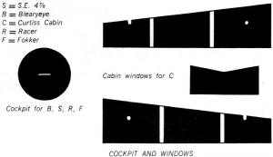 Cockpit and Windows
 Insignias
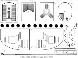 Radiators, Engines and Exhausts
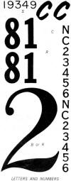 Letters and Numbers Letters and Numbers
It is possible that your model may require a small amount of up- or down-thrust. This is achieved
in exactly the same way as was the right-thrust. If you stop to consider that all this does is to change
the direction in which the propeller points, you will quickly see what, if anything, is needed to make
the model fly properly. Once you are satisfied that the model is flying well, increase the number of
turns in the rubber motor. As the power is increased, some minor readjustments may be required. If you
have a winder, you can really pack in the turns, and greatly improve the performance and duration.
Also, you may wish to experiment with more power, such as a larger size of rubber, or two loops instead
of one. The power can also be varied by changing the length of the rubber loop. A longer loop has less
power, but can take more turns without breaking, while a shorter loop is just the opposite. If the model
habitually falls off on one wing (banks sharply) add a small amount of modeling clay to the opposite
wing. Turn adjustments can also be made by breathing on the rudder and bending it in the direction you
wish the model to turn, but take it easy with this approach. After your. model has been perfectly adjusted,
you may glue the wing on permanently, and throwaway those unsightly rubber bands.
Incidentally, this model recently completed a flight all the way from North Hollywood, California
to Washington, D. C. ... in a box, of course!
Tools
Modeling knife or single-edge razor blade. Ruler or other straight edge. Smooth sandpaper,
such as #400 or #600. Needle-nose pliers for bending landing-gear wire and propeller shaft.
Cutting pliers for cutting music wire. Pencil. Fine-line marker pen for adding decorations if
desired. Straight pins and masking tape for holding parts while drying. A 1/16" diameter drill
bit for drilling the nose block.
Materials
Several sheets of 1/16 x 2 x 36" sheet balsa. (Sorry fellas, I forgot to keep track of how many sheets
I used. Maybe YOU can figure it out from the model.) One piece of 1/32" diameter music wire for
landing gear and propeller shaft. One piece of 1/16'" outside diameter aluminum or brass tubing
for propeller shaft bearing and wheel hub bushings (if required). One pair of wheels about 1 1/8"
to 1 1/2" diameter. Several small washers to use as thrust bearings. (In a pinch, dressmaker's sequins
can be used.) One 5 1/2" or 6" diameter commercially made plastic or wooden propeller. Rubber
strand for power. Recommended power to start: One loop of 1/8" flat Pirelli or one loop of 3/16" brown
rubber. With experience in adjusting, more power may be used. Glue. Scrap of clear plastic sheet
for windshield, if used. Chart tape for decorations, if desired. 1/16" diameter dowels for rear
rubber peg, wing mount pegs, and rigging mast if 1909 Blearyeye is constructed. (May be purchased at
drug store. Ask for swab sticks.)
Miscellaneous
Rubber lube (commercial brand or castor oil). Winder. Not strictly necessary. but will greatly
improve performance. Oil. Automotive or sewing machine oil: one drop on propeller shaft. Caution,
do not allow regular oil to get on rubber band.
 Flying Funtique Plans
Notice:
The AMA Plans Service offers a
full-size version of many of the plans show here at a very reasonable cost. They
will scale the plans any size for you. It is always best to buy printed plans because
my scanner versions often have distortions that can cause parts to fit poorly. Purchasing
plans also help to support the operation of the
Academy of Model Aeronautics - the #1
advocate for model aviation throughout the world. If the AMA no longer has this
plan on file, I will be glad to send you my higher resolution version.
Try my Scale Calculator for
Model Airplane Plans.
Posted September 14, 2013
|