|
Here
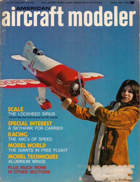
is the article and plans for the Lockheed Sirius that I electronically
scanned from my purchased copy of the April 1973 American Aircraft
Modeler magazine. You might be able to scale up the image below
if you cannot find suitable plans for sale. Plans for this fine
model were drawn by Mr. Maurice F. Philips. All copyrights (if any)
are hereby acknowledged. There were actually two separate
articles, one that covered the history of the
Lockheed Sirius, written by Patricia T. Groves, and the other
this construction article for a scale R/C version. Lockheed Sirius
Article & Plans
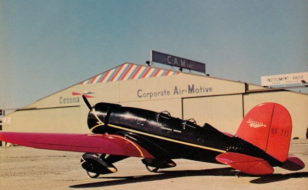
Well-detailed and perfect scale RC version of the Lindbergh inspired
Lockheed design uses foam wings and a glass fuselage. A docile flyer,
too. MAURICE F. PHILIPS The search for a suitable
model to scale and to construct gets more difficult as modelers
continually dig through the files of civilian and military aircraft.
It was surprising to find that the Sirius hasn't recently been built.
Many older modelers remember the famous plane that Lindbergh used
to map out some of Pan Am's early airways. Admiration for the model
of this grand old aircraft of the golden era was expressed by many
of the spectators at the '72 Chicago Nats. Several mentioned that
the model flew just like the full-sized plane they had seen fly
in the 30s. It was pleasantly surprising to find spectator appeal
so high.
There were two friends that influenced my decision to build
the Lockheed Sirius - Monty Groves and Bob Palmer. Both, although
separated geographically, have a common interest in Lockheed aircraft.
The Sirius model results from the combined unique talents
of the three of us. Monty and his wife Patty have researched Lockheed
aircraft for years and has a large file of photographs and technical
data to support their docu-mentation. Bob Palmer, a professional
modeler, has produced several fiberglass fuselage kits of very high
quality. This airplane was a natural for him due to his ability
to reproduce the scale details in epoxy. In making the decision
to com-bine our efforts, it was decided that fiberglass would more
closely represent the original plywood mold construction than conventional
balsa planking over formers. My contribution was to do the scaling,
drawing, and inking as well as to design the construction characteristic
to fiberglass and polystyrene foam.
Lockheed Sirius R/C Model
Fiberglass wheel pants come with the fuselages too and are quite
durable. Note plywood fill-in between inner landing gear struts.
Cowl alignment jig taped in place.
 Below:
Fiberglass cowl has tabs epoxied inside for attachment to firewall.
The model can be flown in Super-Scale or in Stand-off Scale contests.
The Sirius does not have either retractable landing gear or flaps,
thus giving other models a slight advantage in regular AMA or FAI
contests. However' its ability to perform contest stunt maneuvers
does tend to be equalizing. Almost every author attests to his model's
ability to fly on a string. A de-tailed description of the first
few flights will follow later in the text. Construction
In building the fuselage, a Dremel tool IS used
to cut out the cockpit openings and the openings for the horizontal
stabilizer of the fuselage. The tail cone should be cut off using
the minimum cerf. When fitting the stab, it will be necessary to
file the opening slightly. The fuselage tail cone will be epoxied
back after the stab is installed. Mount the radial engine mount
using blind nuts. Note that dimples indicate the centerline.
Do not tap the mount for the engine until the engine is positioned
at 0 degrees side thrust and 0 degrees down thrust. A propeller
was used to assist in the measurement. Measure the drawing to see
how far the thrust washer protrudes past the cowl. Don't forget
the spinner back plate. Construct the plywood brackets that hold
the cowl to the fuselage. Use an extra strong ep'0xy such as 3-M
Structural Adhesive. With an alignment jig position the cowl while
allowing the epoxy to set. After the brackets have been
attach-ed to the cowl, fuel-proof them by coat-ing with Hobbypoxy
II glue. The bat-tery and fuel tank location worked out well on
my model. Cut out two windshields using the patterns. A strong material
can be obtained by removing the copper from a thin fiberglass circuit
board .030 inches thick for the windshield frames. Several jigsaw
blades will be dulled cutting them out. Epoxy them in place with
the 3-M epoxy. A wet finger will form a fillet nicely. Set the fuselage
aside and return to it after completing the rudder, elevator and
stab. Shape the ribs of 'the horizontal stabilizer as shown.
When applying the sheeting, be cautious not to apply a warp. Fit
the completed stab into the fuselage by filing the fiberglass and
sanding the wood. Select soft balsa for the elevators and
shape with a razor plane. Install the horn and hinges matching them
to the stab. Epoxy the stab in place. Install the elevator Gold-N-Rod
at this time. A music wire through nylon tubing will possibly be
less prone to change trim due to heat (if you are worried .about
that sort of thing). Construct the rudder using the same
techniques as for the elevator. After hinging the rudder to the
fin and installing the Gold-N-Rod, epoxy the tail cone back on to
the fuselage. A good filler for the joint is common body-fender
fiberglass epoxy. It can be carved in the leather stage and sanded
when hard. Complete the basic construction of the fuselage
including the tail skid, servo tray, hardwood wing hold-down blocks,
and servo installation. Use Hobbypoxy II glue to secure parts to
the epoxy fuselage. Micro balloons or Cavasill may be added to the
glue when a thicker consistency is required. Cut the three
sections of the wing using the airfoils that are shown on the drawing.
Deduct the skin thickness when making the templates for the hot
wire cutter. Wrap a two-in. wide piece of four oz. glass cloth around
the sheeted wing for a dihedral brace. Push the cloth against the
wood with a roll of toilet paper absorbing excess resin from the
glass cloth. Feather the edges with garnet paper. Prior
to the sheeting, install the aileron horns and linkage system. The
aileron movement should be not more than 3/8" up and 3/8" down.
When making balsa wing skins use resin to join together
the skin sheets. A thin strip of silkspan doped over the inner joint
will prevent its raising after painting. Use a good contact cement
for joining the skin to the polystyrene foam. 3-M No. 77 is very
good, but be careful to allow the thinners to evaporate before attaching
the skin or foam will melt a bit. The hardwood landing gear blocks
worked very satisfactorily, but the plywood plate backing the shock
absorber pivot failed to support rough landings. A proposed modification
will be to insert a piece of No. G-Pad under the pivot to absorb
the shock override. In general, the wing is straightforward foam-balsa
construction.
Landing
gear - The aluminum brackets can easily be cut from bar stock with
a hack saw. With a power drill and file, the bracket is completed
in short time. Bend the 3/16" and 5/32" dia. music wire landing
gears to exactly match the drawing (see front view for front strut).
The fiberglass wheel pants were not available for the prototype,
therefore the first set was formed from balsa. Three pieces of wood
were sandwiched and carved to shape. Plywood bearings were used
for the axles. Epoxy Gel-Cote, unlike polyester, does seem
to have a few pinholes. After cleansing the fuselage with acetone,
spray the exterior with Dupont grey primer. Mix a small amount of
epoxy body filler and push through the holes from the inside of
the fuselage with your finger. After it hardens, sand with 280 wet
and dry sandpaper. Small holes may be filled from the exterior with
thick primer available from the auto parts stores. It may be necessary
to reo peat this procedure until all the holes are filled.
Surprising as it may seem, all the wooden surfaces are covered
with fiber-glass cloth and resin. This is an exceptionally light
finishing method if done properly. Purchase the following materials:
K&B 1/2 oz. glass cloth, Francis Products surfacing resin, single-edge
razor blades, a roll of toilet tissue. Cut a piece of the cloth
slightly larger than the surface to be covered. Using a stiff brush,
apply the resin over the cloth on the balsa surface. Roll out the
toilet tissue over the cloth absorbing the resin. Tear off the end
and peel the saturated paper away from the glass cloth. Be careful
not to pull the cloth away from the wood. Trim the cloth after the
resin has hardened, sand slightly, and apply another full coat of
surfacing resin. After the resin has dried, scrape the sur-face
with a sinqle-edqe razor blade as far as possible without going
through the cloth. Slightly sand the surface with varying degrees
of garnet sandpaper. A coat of auto primer will show any de-fects
to be filled. The drawing shows the CG at 25%, although 32%
is satisfactory. With the short nose moment, the difference re-quired
approximately six more ounces of lead in the nose. My model used
about 14 oz. of lead mounted under the engine mount and in the cowl.
The Williams Bros. dummy engine was cut up so badly that the weight
was negligible. Hobbypoxy was used to paint the model, The
wing, rudder, fin, stab, and elevators were orange while the fuselage,
cowl, wheel pants and fairings were black. Lindbergh's plane had
gold trim on the cowl and fuselage bordered with red pin striping.
Gold dope can be sprayed over the Hobbypoxy if the spray is mist-like.
A heavy coat will cause the Hobbypoxy to blister and peel. Be very
careful in removing the tape from the fuselage, as there is a ten-dency
to peel the paint away from the epoxy fuselage. This can turn a
mild tempered modeler irate, raving and swearing. The first
flying attempt was a dis-aster followed by many successful, pleasing
flights. Dr. Les Stephenson, Ralph Young and I decided to give the
Sirius its maiden flight at the Hollister airport. A warm 102 degree
day was chosen for the test. The Enya II engine and Perry carburetor
performed flaw-lessly, idling at 2700 rpm for as long as required.
The tail picked up with the first burst of power and the model
made a sudden turn. to the left. The correction with my left thumb
must have accidentally applied elevator and it cartwheeled. The
nylon bolts sheared from the cowl mounts and the wing tips were
scuffed. Other than a few small cracks, the damage was minor. Two
adjustments were made. The elevator throw was decreased and full
right rudder trim was used for takeoff. Once airborne, the trim
was removed. This countered the torque, although there was a tendency
to steer to the right. The next five flights were made at
the '72 Chicago Nats. where it flew even better than I had expected.
The roll is slow and in loop it tracked perfectly. The landings
were easy to control which is probably due to the thick Clark Y
airfoil. The Gold-N-Rods tended to change trim in the black fuselage
when the temperature rose. The next model will probably have music
wire running through the nylon tubing. When the. engine was
"honking," I found the nine-lb. wonder did not perform at at all
like a heavy model. It was an easy, fun to fly model. The director
of the airshow, at the '72 Nats, asked me to fly it for the spectators.
Many of the people showed their admiration by thanking me for taking
part in the exhibition. This was personally very re-warding.
After taking a dozen orders for the kit, I realized that this
vintage aircraft model left a little nostalgia with the spectators.
My time has been well spent. The modeler wishing to purchase
the fuselage may send an inquiry to Bob Palmer, 9161 Morehart Ave.,
Arleta, Calif. 91331.
 Lockheed Sirius Plans
<click for larger
version>
Lockheed Sirius 3-View
<click for larger
version>
Notice:
The AMA Plans Service offers a
full-size version of many of the plans show here at a very reasonable cost. They
will scale the plans any size for you. It is always best to buy printed plans because
my scanner versions often have distortions that can cause parts to fit poorly. Purchasing
plans also help to support the operation of the
Academy of Model Aeronautics - the #1
advocate for model aviation throughout the world. If the AMA no longer has this
plan on file, I will be glad to send you my higher resolution version.
Try my Scale Calculator for
Model Airplane Plans.
Posted June 16, 2010
|