|
A website visitor wrote to ask that I scan and post this article
for the Patriot rubber-powered free flight model. It is a simple
stick and sheet balsa job that can be built for about three bucks
worth of parts. The wings uses a couple ribs on the underside to
form an undercambered airfoil for a little extra lift. Enjoy!
The Patriot
It can't lay an egg, it's an all-balsa bird.
David Garrett
ROG's, I think, can best be described as "fun" models. They are
simple to build, cost little, and can be flown most anywhere. The
abbreviation, incidentally, means "Rise-Off-Ground." Light weight
enables them to take most bumps and knocks without serious damage,
and when properly trimmed, their flight pattern is smooth and steady,
from the first burst of power, to the final dead-stick landing.

Patriot is all of these. She is fast under power, steady in the
climb, and most graceful and flat in the glide. But I think you'll
see what I mean when you've finished building your Patriot.
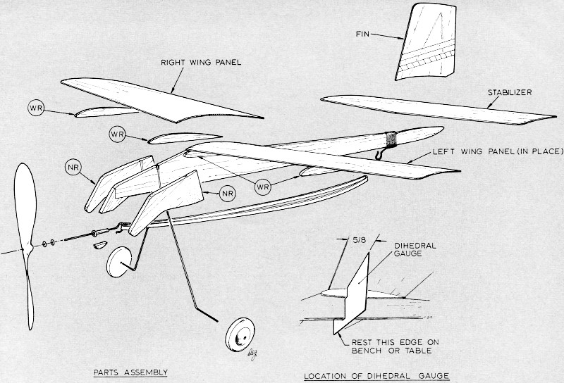
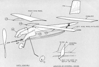
Construction: Before cutting material, look
at the plan, starting with the illustration in the upper left-hand
corner. The fuselage is composed of four parts, PC1, main fuselage,
PC2, nose, and two PC's NR, all of which are cut from the piece
of 1/8" sheet.
These parts are assembled with the addition of the landing gear
and eyelet as shown to form the nose section. (PC6 need not be cut
out, but use scrap 1/8 sheet to fill the space after the eyelet
is in place.) Notice that there is a notch in the top edge only
of the fuselage. This notch enables the landing gear to fair in
with the nose. Each one of the PC's NR is notched on the inside
only in order to accept the landing gear and retain it firmly after
being glued in place.
Note also that NR is to be cut to the curve indicated by the
arrowhead between PC1 and PC2. (Make sure when cutting out the parts
that the grain runs in the direction shown on the drawing.)
The next piece used on the fuselage is the wing rib WR. Four
of these are required and are cut from the piece of 1/16 sheet.
Two of these pieces are glued to the fuselage, one on each side
of the wing mount. The two remaining pieces are cemented to the
underside of each wing panel at the location shown on the plans.
Two wing panels are required, and are cut to the shape shown
on the plan. The stabilizer and fin are conventional. The wing panels,
stab, and fin are cut from the 1/32 sheet.
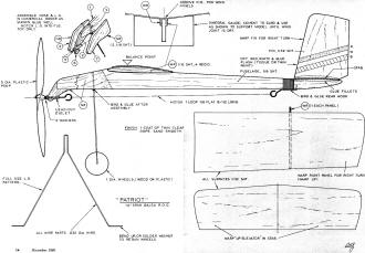
The landing gear, prop shaft, and rear hook are bent from the
1/32 dia. wire to the shape indicated on the plan. The prop shaft
is bent back after the propeller and washers are placed on the shaft.
Transferring patterns from the plan: There are
a couple of methods by which parts outlines can be transferred to
wood. The first method which is sometimes used is to place a sheet
of carbon paper between the plan and the material. The outline of
the part on the plan is then drawn over with a sharp pencil and,
by means of the carbon paper, the outline of the part is transferred
to the wood. The disadvantage in this method is keeping the plan
and the material from moving. One slip and you have to start over.
The second method, which I prefer, gives you greater accuracy and
easier handling of the patterns. With this method, the part drawing
itself is cut directly from the plan, placed on the wood, and then
is outlined by means of a ball-point pen.
One thing to remember, however, is that when the parts are cut
from the plan, cut them out leaving the outline showing. However,
when the part is outlined on the wood, I'm sure you will notice
and probably say, "The wood part is going to be bigger." Not so.
When you cut out the wood part, cut to the inside of the outline
of the part drawn on the sheet. If you do this carefully, you will
have an exact duplicate of the part. This is where the straight-edge
or triangle will be an asset. Use either for all your straight cuts
of any length, being careful to keep your knife straight up and
down. Another important thing to remember is, don' always try, or
expect, to cut through the thicker stock on the first try. You'll
get bet-ter results and take less chance of being cut by a slip
of the knife, if you take it easy.
On this particular model I'd recommend tracing the piece NR first.
Cut this to outline and transfer it to the wood by drawing around
the tracing as described above. If you don't trace it first, you
might find yourself out of luck finding a complete pattern to use,
because of your cutting out the fuselage outline first and, at the
same time, taking part of NR with it!
When cutting out the fuselage pattern, remember that the outline
at the wing mount is the same as the top line of WR. When cutting
out any curved parts such as the wing panels and stab., cut your
curves first, and then, using the triangle or straight-edge, join
the straight cuts to them. Another point is to center the wing panels,
stab. and fin on the sheet when outlining. Make your cross-grain
cuts first, extending them past point where they cross with-grain
cuts.
If you make the with-grain cuts in the same manner, the parts
should come out nice and clean. Choose your method and start cutting.
A small sanding block or emery board is very useful in dressing
up parts after they are cut out.
A dihedral gauge is provided on the plan to insure alignment
of the wings and fuselage. Use it; it's important. I would also
suggest pre-glueing of the parts before assembly. It makes a stronger
bond. To pre-glue a part, rub a bit of cement on the edges that
are to be joined, and let dry. Then apply additional cement and
join together.
Assembly: Starting with the fuselage, assemble
the nose parts as shown on the plan. Pre-glueing is important here.
The eyelet will not come out if the assembly is left to set well.
When the nose section is set, round off the corners and put a slight
taper on the pieces NR.
The fuselage's WR's' are cemented on next, making sure to keep
them flush with the hump in the fuselage. When these are dry, cut
the shallow "V" groove in the top of the fuselage for the wing panels.
The rear hook is mounted next, taking care that the thread binding
does not wander in the area where the stab. mounts. If it does,
and is not corrected, the stab will be put out of the trim when
it is cemented on. Rub glue on the thread as you wind it; also cement
again when your binding is finished.
The wing is assembled next. Before mounting the wing panels,
cement a WR in place on each panel and let dry. When this is done,
apply cement in the groove, rub in, and let dry. When ready, apply
cement to wing panel (either one) and set in groove. When cement
is almost set, put the other panel in place and hold with pins.
Now position the model at the edge of the bench or table in such
a way as to let the landing gear hang over the edge. Place the dihedral
gauge under the plane so it supports the wings and fuselage. (Apply
glue fillets to the wings and fuselage when this assembly has set.)
Replace in the dihedral gauge and let dry. Remove the pins when
you are sure everything is set. (Sometimes when applying fresh glue
over old, the old glue will soften and release whatever it is holding;
don't sweat it, just watch for it and make whatever adjustments
you have to, until everything is set again. The time is worth it.
Before mounting the stabilizer, lay the pattern over it and make
a small cut in the stabilizer at each end of the centerline. These
cuts are reference marks to be used when cementing the stabilizer
to the fuselage. Before the glue sets, make sure the marks in the
stabilizer are centered on the fuselage. These same marks will also
be an aid for positioning the fin. Check the marks alignment of
the tail assembly to make sure that the stabilizer is square with
the fuselage, and also that the fin is vertical.
The wheels now are installed. When all the parts have set, round
off the edges of the fuselage with the sanding block. With fine
sandpaper, sand the completed model and apply one coat of thin dope.
Sand again when dry.
Motor and propeller: Insert the prop shaft through
the eyelet, the two washers and the propeller, and bend back as
shown on the plan. The motor is made from one loop of 1/8 flat rubber
strip, 8 1/2 long. Cut the rubber to length, and tie a square knot
to join in a loop.
Put one end of the loop on the prop shaft, adjusting it so that
the knot comes somewhere about the middle of the fuselage, then
place on rear hook. The motor, when installed, should hang slightly
below the fuselage.
Before winding the motor, I suggest that you secure some green
soap and glycerine from your local drug store. From these a half-and-half
mixture is made. This becomes a lubricant for the rubber. Rub a
small amount on the motor before winding. The motor will last longer,
wind better, and give you much more rewarding flights.
Balancing: A pin should be inserted at the balance point indicated
on the plan and adjusted so that the pin comes straight up out of
the point indicated. Then note to see how the model hangs. If it
is nose-heavy, weight should be added to the tail. If it is tail
heavy, add weight to the nose.
The bottom of the fuselage should be level when correctly balanced.
The best method for adding weight I have found is the using of small
pieces of wire solder cut to a length that might be suitable and
placed on the nose or tail where needed. When the correct length
is determined, it may be notched into the wood where feasible, and
glued well.
Initial glide trim: Patriot is fitted with a
"lifting" stabilizer. In this form, the stabilizer contributes lift
in order to hold the tail up, so to speak. Under power, this configuration
gives less drag and helps to push the plane along. However, if too
much lift is generated, the tail plane could override the wing lift
and put the plane into a steep dive. In order to counteract this,
a little up-elevator should be warped into the stabilizer. This
should be done before test glides are made.
Test glide until a flat glide is achieved when the model is launched
with a moder-ate push towards a point some 20 feet in front of you.
This flatness of glide is mainly governed by the stabilizer, so
take the time to do it, and adjust the up-warp to suit.
If, during glide tests, you notice the model falling off to the
right or left, correct it by warping the wing tip, or "aileron"
up on the side opposite to the direction of fall.
Flight characteristics: The flight pattern under
power generally will be a steady climb to the right to a height
of about 25 or 30 feet, or more, depending on motor winds. As the
thrust reduces, she will fall off slightly in a left bank and settle
either into a long flat glide, or a figure-8 pattern, depending
on your individual trim preferences.
The warp notes on the plan were as used on the model shown. These
will vary with each individual's preference. At any rate, she does
fly when trimmed out and is pretty to watch. I would recommend,
however, that a right climbing turn be sought when trimming, in
order to minimize propeller torque.
First flights: When the glide is satisfactory,
wind the motor up to about 100-150 turns, and launch slightly nose
down, after letting the prop go for a few "revs." This propeller
action creates a slipstream which helps greatly in the launch. Do
not, however, throw the plane up in the air.
After a few flights, decide on the trim desired and try winding
the motor up to about 200-250 turns or so, and let her go. I think
that, if you've trimmed it right, you'll be very pleased with the
results.
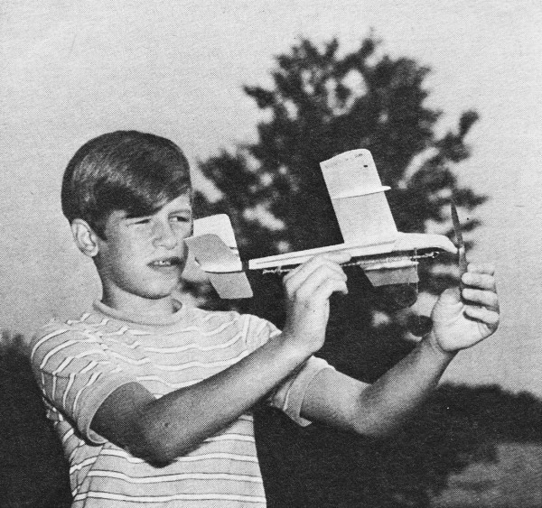
Hand-launching the Patriot gives very good flights - as far as
ROG is concerned. I don't have a good runway, so I've been doing
most flying by the hand-launch method.
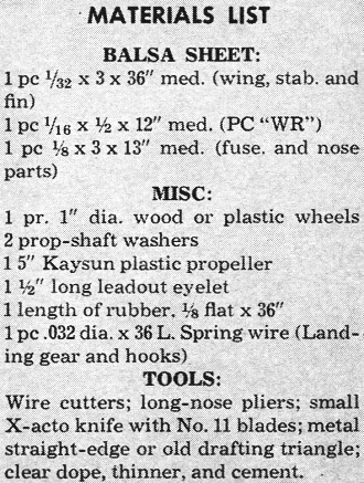
Materials List
Balsa Sheet:
1 pc 1/32 x 3 x 36" moo. (wing, stab. and fin)
1 pc 1/16 X 1/2 X 12" med. (PC "WR")
1 pc 1/8 x 3 x 13" moo. (fuse. and nose parts)
Miscellaneous:
1 pr. 1" dia. wood or plastic wheels
2 prop-shaft washers
1 5" Kaysun plastic propeller
1 1/2" long leadout eyelet
1 length of rubber, 1/8 flat x 36"
1 pc 0.032 dia. x 36 L. Spring wire (Landing gear and hooks)
Tools:
Wire cutters; long-nose pliers; small X-acto knife with No. 11
blades; metal straight-edge or old drafting triangle; clear dope,
thinner, and cement.
The Patriot Plans
Notice:
The AMA Plans Service offers a
full-size version of many of the plans show here at a very reasonable cost. They
will scale the plans any size for you. It is always best to buy printed plans because
my scanner versions often have distortions that can cause parts to fit poorly. Purchasing
plans also help to support the operation of the
Academy of Model Aeronautics - the #1
advocate for model aviation throughout the world. If the AMA no longer has this
plan on file, I will be glad to send you my higher resolution version.
Try my Scale Calculator for
Model Airplane Plans.
Posted July 28, 2015
|