|
Can you imagine what a sweet
sound it must be with four Cox .049 engines running at the same time on the same
airplane? Keith Laumer and John Simmance didn't have to wonder once they teamed
up to design, build, and fly this 45" wingspan, control line B-17 Flying Fortress.
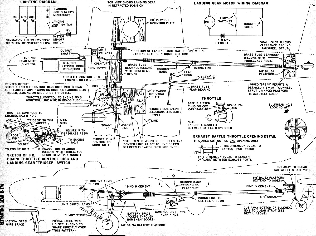
As if that wasn't enough, they added a custom electrical retractable landing gear
(including the tail wheel), navigation lights, throttles on all four engines, and
flaps! An 800:1 reduction gear box was coupled with a 3 volt motor to drive
the retract mechanism, flaps, throttles, and light switches. A third control line
and a Roberts 3-line bellcrank controlled everything. Operation of the retracts
is a bit dicey since they are triggered to go up at full throttle, then go back
down at low throttle. That means the pilot has to be careful not to command full
throttle while the model is on the ground or the landing gear will fold up on him.
I would not have wanted the task of trying to get all four Babe Bee .049 engines
running at the same time. Today we have commercially available electric starters
for the small engines, but in 1963 when this article appeared in American Modeler
magazine, it was either use the spring starter on the engine or flip it by hand.
Boy, do I remember those days! Retracting Gear B-17G Control Liner
British scale champ and noted American designer team up to produce
fabulous 4-engine bomber with working flaps and landing gear, lights, even motor
control!
By Keith Laumer & John Simmance
We could begin by discussing the fantastic record of the airplane that started
life as a heavy bomber and ended the war classified as "light" by contrast with
the bigger, more modern aircraft that had come to supplement - but never to replace
it -
But we won't. We picked the B-17 as our scale project because it's a model builder's
dreamship; sturdy, straightforward, handsome - and a born flyer that will ride in
on one engine just like the big ones.
You can build her with fixed landing gear and two engines plus two dummies -
or go all the way with four operating mills, retracting gear, operating flaps, navigation
and landing lights, throttle control, and little men in the cockpit. Either way,
she's a project that will keep you off the streets for quite a few evenings - but
she's worth it. The ship is not recommended as your first scale project. But there
are no unusual techniques, tools, or materials required.
Spend an hour looking over the plans, then begin construction by laminating main
and rear spars and making leading edge, taking care to build-in correct sweep-back.
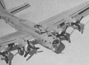
B-17 control line model uses four Cox .049 engines.
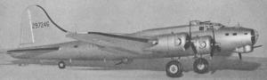
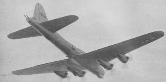
Side view of B-17 with retractable landing gear.
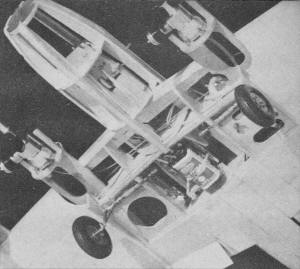
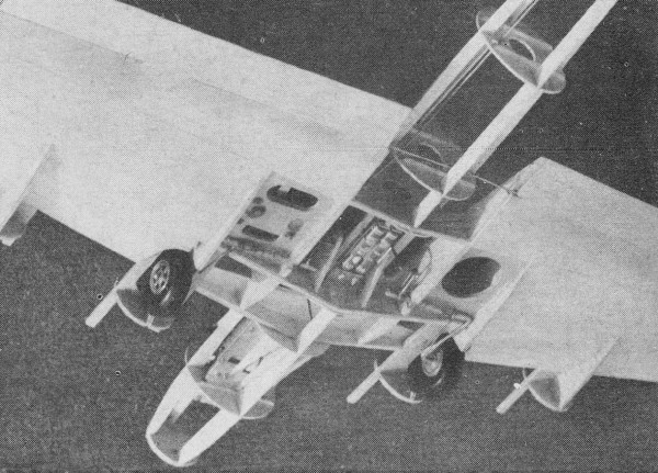
Working landing gear mechanism is shown above in "down" position.
Designer Laumer went all out on this Flying Fortress project.

Gear is retracted. Mechanism, made up of generally available
parts, presents a real challenge to the advanced U-control fan.
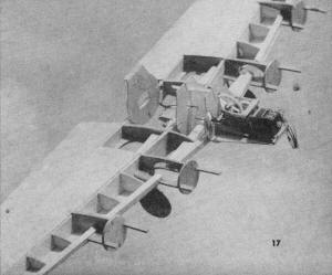
Builder of this B-17 is John Simmance, British free flight scale
champ for past two years; model will fly in '63 C/L events.
Cut out all wing parts, then thread ribs A-E onto component "N" using slow drying
white glue; add L.G. mounting plates and main and rear spars, then component "0."
Align and set aside. When thoroughly dry, add remaining ribs and leading edge. Add
trailing edges in front of flap and aileron stations, then use 1/16" sheet to cover
the wing on both upper and lower surfaces aft of the rear spar, on upper surfaces
only between main and rear spars, and on undersurface only forward of main spar
to leading edge. Sheeting should be doped with clear fuel-proofer before installing.
Build the main gear assembly, using any suitable electric motor and gear train.
Install main L.G. legs and center operating yoke assembly by binding and cementing
brass bearing tubes to supporting plates. Use a stick-anything glue for this step.
Add both formers 3 and 4 to center section, then upper fuselage spine and former
2, followed by main L.G. unit already mounted on its 1/8" ply supporting platform,
gusseting everything well with scrap balsa.
Build up fuselage by half-shell, add side numbers 15-17, and join to wing, cutting
16 away at main spar. Cut away bottom keel behind main spar hack to former 4 to
form "bomb-bay" battery compartment. Check alignment of the entire assembly and
allow a few hours for cement to set hard.
The linkage from gear unit to L.G. is made and installed along with tail wheel
assembly and push-rod from main gear. Nacelle components are cut and glued in position
- cut away leading edges where indicated on inboard nacelles only.
Install bell-crank, lead-outs, elevator push-rod, throttle controls, trigger
and limit switches and L.G. wiring.
Sheet undersurface of wing between spars; add 1-oz tip weight to starboard panel,
then add flaps and linkage and connect to L.G. push-rod.
Start fuselage planking with one strip of 1/8" x 1/4" medium soft balsa along
each of the upper and lower spines and side members.
Construct and install stabilizer unit and elevators and connect to push-rod from
bell-crank. Use lightweight balsa for all tail components.
Railroad type "grain of wheat" light on short pigtails are wired in, together
with all wiring and main and landing light switches. All switches are made from
small pieces of printed circuit board and thin brass, the landing light switch being
closed by the L.G. yoke arm when in "down" position, the main switch being rotary
in action operated by a small screw head. Access with a screwdriver for switching-on
is through an 1/8" diameter hole in the underside of the wing center section.
Batteries are installed and all systems tested.
If necessary, bolt sheet lead behind former 1 until model balances one inch forward
of main wheels in down position.
Complete fuselage planking, wing sheeting, nacelle planking; add soft block tail
end, fin and rudder, wing tips and ailerons. Complete the fitting of navigation
and landing lights and glaze landing light apertures in wing leading edges.
Fill in nose section, cabin, and fuselage top glazed sections with soft balsa,
lightly cemented in place so that these parts may later be cut away to be used as
molds for the acetate canopies. Make separate molds for the gun turrets and tail
gunner's station.
Sand entire aircraft smooth, apply 3 coats of sanding sealer, sanding well between
each coat; build up wing and stabilizer root fillets with Plastic Wood.
Break out balsa canopy mold sections, mount firmly on 1" x 1" balsa hand grips,
dope and polish glass-smooth and mold all acetate sections.
Cut out all windows from fuselage planking and dope matt-black all interior woodwork
visible through windows and canopies. Fit cockpit details, pilots; fit all canopies
and gun turrets and glaze windows with acetate sheet. With masking tape or adhesive-backed
plastic sheet, cut out and fit individual clear area window masks over all acetate
sections. This will take a little time but it's the only way of achieving a really
professional job.
Spray all unmasked acetate sections light grey or green to give the appearance
of internal paint color. Fill and sand smooth all cracks and imperfections around
glazed areas.
From now on all work will greatly affect appearance of finished model, so take
time to insure a good finish.
Build up cowlings from balsa, fit to nacelles and seal and dope. Sand entire
model smooth again. Cover model all over with lightweight silk or paper, and apply
three more coats of sanding sealer, then at least three coats of clear dope, thinning
dope progressively each coat to achieve a really good basic finish. Dope should
be sprayed, but a careful brush job will do. Use fuel-proof dope throughout.
Apply thinly sprayed color dope in any authentic scheme. Many photographs are
available with either all-aluminum or olive drab finishes. If you choose an olive
drab finish, then another cry from a scale modeler's heart: do not forget to apply
a final last coat of clear matt varnish - please, NOT glossy!
When all color is on, together with serial numbers and markings, masks may be
removed from glazed areas. Fit guns from aluminum tube, windshield wipers from straight
pins and aerials from thin nylon thread. Test all systems and free up any working
joints that may be clogged by dope.
With India ink and a fine pen, draw hatch detail onto model, taking care not
to overdo it.
Points to watch to achieve a good finish: (1) Clean dope. (2) Clean, dust-free
brushes. (3) Clean, dust-free room, not too cold. (4) Clean, dust-free model - wipe
off frequently with clean cloth. (5) Let all coats dry before applying next. (6)
Make certain basic structure and clear dope finish is really good before applying
color, which should be sprayed on lightly. Two coats of color dope should be enough.
This saves a lot of weight! (7) Don't panic! Take your time! The model will not
go together in three evenings, but the finished job is worth the trouble.
Final weight trim is achieved if necessary by drilling a small hole underneath
the chin turret, filling with cement and lead shot, until the model balances on
the leading edge just outboard of the nacelles. This hole is easy to plug without
marring the finish.
Test all systems again on the flying field, with lines connected and all engines
going, once you have recovered from the effect of those four Cox's running wide
open! This model not only looks like a B-17, it sounds like onel! Test throttle
response, adjusting so that starboard engines throttle down more than port engines.
Open throttles wide, and as soon as L.G. starts up, close throttles slightly. This
will stop L.G. on limit switches but has no noticeable effect on engines. Bring
L.G. down, stop engines, fuel up and flight test.
Allow model to taxi out and keep her on the ground until speed is well up, then
"up" elevator may be applied on ground run to prevent nosing over, but neutralize
as soon as she lifts off. From then on you're on your own, but you will find the
B-17 easy to fly and "groovy". And the joy of being able to haul those big wheels
up forward into the nacelles, and as the third engine falters to bring down the
wheels and touch down again for a perfect landing, applying up elevator again as
soon as she rolls. Approaches are easy on low throttle, the engines still running
fast enough to give good control.
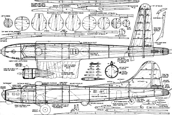
Retracting Gear B-17 Control
Liner Plans: Fuselage
<click
for larger version>
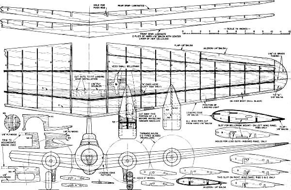
Retracting Gear B-17 Control
Liner Plans: Wing
<click
for larger version>
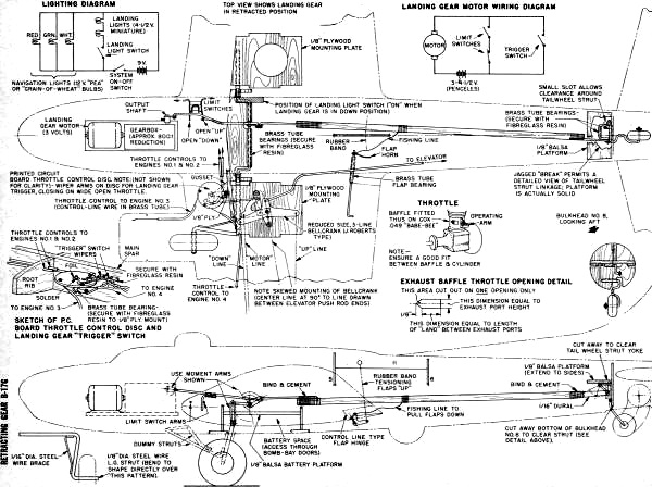
Retracting Gear B-17 Control
Liner Plans: Retracting Gear Detail
<click
for larger version>
Notice:
The AMA Plans Service offers a
full-size version of many of the plans show here at a very reasonable cost. They
will scale the plans any size for you. It is always best to buy printed plans because
my scanner versions often have distortions that can cause parts to fit poorly. Purchasing
plans also help to support the operation of the
Academy of Model Aeronautics - the #1
advocate for model aviation throughout the world. If the AMA no longer has this
plan on file, I will be glad to send you my higher resolution version.
Try my Scale Calculator for
Model Airplane Plans.
Posted April 13, 2022
(updated from original post on 9/30/2012)
|