|
Oddly enough, this extremely long article on Al Rabe's famous Sea
Fury control line scale stunt model does not include plans. I checked
the
AMA Plans Service website and do not see plans listed there,
either, so unfortunately for anyone wanting to build this model,
there won't be any help available from the AMA. The main purpose
of this article seems to be the extensive research and empirical
testing Al Rabe did with airfoils, planforms, control surfaces,
etc., in arriving at his final winning design. He even performed
live runs of test airfoil sections to determine lift and drag with
and without flaps. I scanned this article at the request of an
Airplanes and Rockets website visitor
who hoped to get plans, but no can do. Dang.
Control Line Scale Sea Fury: Go For Broke
Designed & Photos by Al Rabe
Most controversial stunt model is full of new construction techniques,
up-to-date aerodynamics, engine/muffler ideas, and ample trimming
capability.
Little did I realize a year and a half ago as I sat studying
the FAI rules that 1971 was going to be a "go for broke" year. At
that moment I was feeling helpless frustration. It was an FAI qualification
year and, according to the rules, mufflers would be required. I
think most stunt fliers dread the thought, initially at least, of
using mufflers as they add weight, rob power and cause cooling problems
without improving, in any way, an airplane's ability to fly a pattern.
I was particularly upset as my semi-scale Mustangs and Bearcats
tended to build heavy. Also, for optimum performance, even the lightweight
Bearcat III needed all of the power that an ST 46 could offer. Since
my current airplanes could afford neither the weight nor power loss
of a muffler, clearly, a new airplane was needed, designed to FAI
rules.

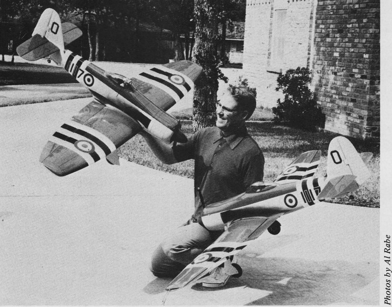
1972 AMA Nationals Stunt Winner Al Rabe with
His Sea Furys
Because of the power loss, this new airplane would either have
to be smaller to use the very fine ST 46, or about Bearcat size
with a larger engine. In general, Bearcat size airplanes have a
slight advantage over smaller airplanes because of slightly more
favorable Reynolds number and usually a somewhat better visual impression.
I therefore decided to build the Bearcat size airplane and use the
lightest 60 available having the necessary conservative porting
and reasonably long stroke. This narrowed the choice to the ST 60
at 12 ounces (with venturi, not carburetor).
The extra weight of a heavier engine, larger tank, extra fuel,
muffler and stronger nose structure dictated that my new stunt ship
should have a short nose and could possibly profit from a longer
than normal tail moment. After spending a few hours looking at Green's
Famous Fighters of World War II, I found several airplanes which
would make excellent semi-scale stunt ships by profiting heavily
from the above-mentioned nose and tail moment changes. The Spitfire
and Hawker Tempest V seemed the most ideal with the Tempest V having
the edge because it offered the possibility of enclosing the muffler
within a large "chin" radiator. When I drew up the Tempest V, the
nose was so large that the ST 60 cylinder head didn't even extend
into the "chin" radiator area. As a matter of fact, at that scale,
the engine and muffler would go into the radial cowling of the more
attractive Tempest II. From there I couldn't help but notice the
Hawker Sea Fury which has the same wing and cowling as the Tempest
II, better lines, and a colorful service paint scheme. To the disadvantage
of the Hawker airplanes were their wings which have outboard dihedral
breaks. After a couple of weeks of stewing over the immensity of
the project I decided to "go for broke." Win or lose, I was going
to build my muffled airplane and would somehow manage to make it
more realistic than previous semi-scale designs.
Building a heavier, more realistic airplane would be possible
only if ways could be found to significantly increase the lift of
its wing. As it happens, I have been using an airfoil test rig for
about three years, and based upon experiments with different airfoils
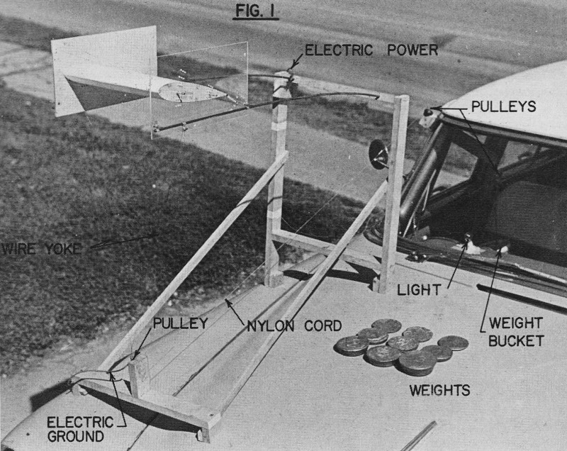
I was sure that extra lift was attainable. (Fig. 1)

Figure 1 - Airfoil test rig. All runs late at
night on straight, smooth stretch of back country roads.
Since my experiments may be of interest to other modelers and
provide background for the development of the Sea Fury wing, I will
chronologically explain the results of these experiments. Airfoil
tests were necessary because there is little NACA airfoil data available
at Reynolds numbers of less than three million (Rn 3
x 106). Because our stunt ships operate at Reynolds numbers
of less than a half million, air is relatively much more viscous
making most NACA data concerning coefficients of lift, drag, and
pitching moments practically useless. To obtain usable performance
data I ran tests on model size stunt sections at stunt speeds arid
used a Nobler test section for comparisons. From my first tests,
I found that: Nobler sections produce more lift with 20° of
flap than with 40° of flap, probably due to flap stall (optimum
flap is near 30°); wider flaps provide more lift; sealing a
rather wide hinge gap produces no significant improvement; turbulators
installed at 10, 15 or 20% chord neither help or hurt lift measurably.
These findings should apply to nearly any 20% symmetrical airfoil.
(Fig. 2)
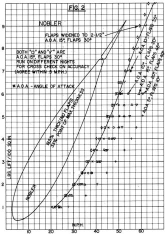
Figure 2 - To investigate UC Stunt airfoils,
one must begin by understanding the best available "classic" airfoil
- the·Nobler.
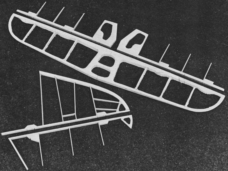
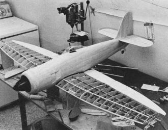
Cores for 1/16 sheeted tail surfaces. All these
assemblies, as shown, weigh .4 oz.
The Sea Fury's shock absorbing gears and Rabe's
method of lacing them to their mounts with .032 aircraft brass safety
wire. Will never loosen at all.
Method of assembling molded fuselages. Second
half is still on mold. Most sanding done while on mold. Four aft
bulkheads laminated 1/32" ply 3/32 balsa. Note tailwheel mount installed.
Next, I designed my first "super" airfoil. It was a built-in, "simple"
flap type where the flap forms the aft contour of the wing much
the same as Keith Trostle used on his Nats-winning Focke-Wulf Ta
152. I tried to go Keith one better and use a full-scale aircraft
practice of moving the flap hinge line slightly aft. When this flap
moves down, the ,nose of the flap moves slightly upward, closing
the hinge gap and projecting a slight "bump" at the hinge line.
This "bump" in full-scale aircraft improves maximum lift by reattaching
the separating boundary airflow as the airfoil nears stall. I was
so convinced this wing would offer an improvement over the Nobler
type that I designed my first super semi-scale stunt ship around
it. It was to be a T-28B with an exact scale fuselage from North
American lofting data obtained from Dave Platt. Imagine my surprise
and disappointment when tests showed that, in spite of the more
sophisticated hinge location, my "super" airfoil performed about
10% poorer than the smaller, thinner Nobler airfoil plus its sheet
flap. (Fig. 3)
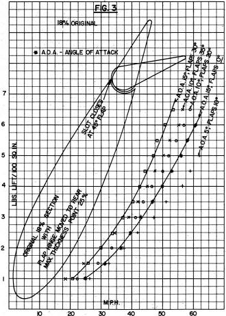
Figure 3 - A "simple" type flap. Harder to build,
nearly impossible to properly hang and 10 to 15% less efficient
than Nobler airfoil with sheet flap.
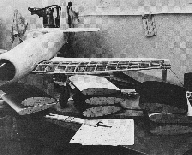
Airfoil, test sections actually used to prepare
graphs.
To find the reason for my "super" airfoil's poor performance,
I researched about 30 years Of NACA Technical Reports and found
that "simple" flap airfoils at Rn 3 x 10⁶
produce a CL Max (maximum .coefficient of lift) of about
1.6 (call it a figure of merit). "Fowler" flaps can produce a CL
Max of about 2.8 at Rn 3 x 10⁶. Although a
"Fowler" flap moves to the wing trailing edge while extending (which
our stunt ships can't duplicate), the fully extended "Fowler" flap
that produces this CL Max of 2.8 looks much the same
as our stunt airfoils with a depressed flap hinged to the wing trailing
edge. So, while our sheet flaps aren't retractable, they do appear
to have the lift capabilities of the "Fowler" flap. At this point,
I removed my T-28B ribs from the jig, put away the plans, and packed
the rifle-barrel-like molds I had machined to form molded" balsa
flap leading edges. The T-28B project was dead - that air-plane
just wouldn't look right with a larger wing.
In my NACA studies I also found flaps work better on thicker
airfoils than thin airfoils, I suppose because the airflow is better
directed across the hinge line and flaps. My own tests showed that
a flapped stunt airfoil lifts about half again more weight than
a no-flap airfoil of the same total chord length. (Fig. 4)
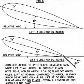
Smaller airfoil "B" with flaps develops 50% more
lift than airfoil "A" without flaps. Note Fig-2, Nobler airfoil
A.O.A 15°, flaps 30° makes 6 lbs. lift at 50 MPH compared to
airfoil in Fig-3 which developed only 4 lbs. lift at 50 MPH when
run at A.O.A. 15° NO FLAPS. Overall length of both airfoils is the
same.
At this point I built my very successful Bearcat III utilizing
a molded balsa fuselage and making two very significant changes
in the wing layout. First, because. of the NACA studies, I profiled
the aft portion of the Bearcat III rib to transition more smoothly
into a deflected flap by adding curvature from the spar aft as opposed
to the relatively flat shape of the Nobler rib. Second, from my
own tests, without changing the overall shape or the area of the
wing, I relocated the Bearcat's flap hinge line, angling it forward,
so the flap would maintain a constant percentage of the wing chord
instead of narrowing to insignificance as it approached the wing
tip."This straight trade of wing area for flap area increases the
lift of the wing tips by about 50% and accounts for about a 20%
overall improvement in the total lift capability of the wing. This
effect was also verified by modifying the original Bearcat I to
increase its flap area by cutting away the trailing edge of the
wing at the tips and building new, larger flaps. This modification
noticeably improved the Bearcat I's corners and was incorporated
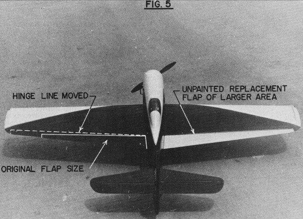
into the American Aircraft Modeler plans. (Fig. 5)
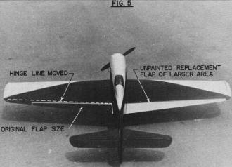
Bearcat I modifications. It's never too late
to cut into a good stunt ship to improve its performance. Bearcat
I had 950 logged flights when this modification was made.
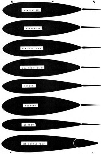
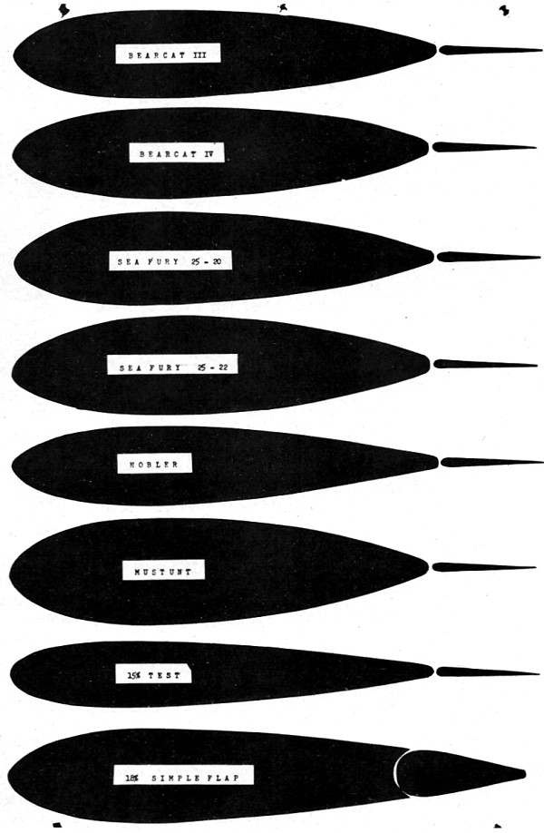
Airfoils presented here are 25% of original size.
Next, I found an NACA graph of CL Max of symmetrical
airfoils of various thicknesses, with and without flaps. (Fig. 6)
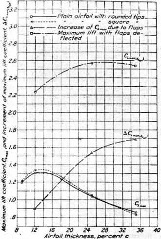
Figure 6: Variation of maximum lift coefficient
for an airfoil, with and without flaps, and increment of maximum
lift coefficient due to flaps with airfoil thickness for three NACA
airfoils. Reynolds number, 3,000,000; aspect ratio, 6.
This chart shows what many stunt fliers have read for themselves
in various publications - a 12 to 15% symmetrical section will give
maximum lift. But that is true only without flaps. This graph also
shows that flaps work better on thicker airfoils. Highest CL
max were obtained at approximately 28 to 32% thick sections with
flaps. To test this at model size I built a 25% test section and
found that it did indeed produce substantially more lift. Using
this big improvement in lifting capability, I designed the Mustunts
I and II for the novice stunt fliers to help them lick problems
with weight. (Fig. 7)
Figures 7 and 8 show improved lift attainable
by increasing thickness of airfoil.
Now I was ready to design the Sea Fury wing. I knew that to carry
the Sea Fury's weight I was going to have to use large flaps and
a 25% section. Take your choice, the wing would have to be either
big or thick. Wait a minute! The AMA stunt pattern itself is asymmetrical
requiring far more lift for the lower right triangle and hourglass
corners than anywhere else in the pattern. Since these are both
inside corners I should be able to get away with an asymmetrical
airfoil with a 25% curvature on the top of the wing and a flatter
20 to 22% curvature on the bottom for the less demanding outside
squares. By tailoring the airfoil to the lift requirements of the
pattern, I could have my high lift characteristics and still slightly
reduce the bulk of the wing. Again, I decided to "go for broke"
and use the completely untried asymmetric airfoil concept on my
Sea Fury to improve the appearance of the wing. At this point I
built two new asymmetric test sections and waited six weeks for
a calm wind night to test them (I live in Texas, you know). Finally,
in desperation, I ran the tests in an eight-knot wind - I just had
to get started building the Sea Fury wing.
While tests under windy conditions must be inaccurate, I still
felt they would be useful indicators of relative performance. Sure
enough, the airfoils tended to group on the graphs into families
related by thickness. The 25% sections all performed 35 to 40% better
than the best of the 18 to 20% Nobler and Bearcat airfoils. Clearly,
thickness is far more important to airfoil lifting capability than
any other characteristic such as profile or leading edge radius.
(Figs. 7 & 8)
To explain my asymmetrical airfoil designations, the Sea Fury
25-20 has a top of the airfoil similar to the top half of a 25%
symmetrical section. The bottom half of the Sea Fury 25-20 is similar
to the bottom half of a 20% symmetrical airfoil.
The Sea Fury 25-20 test section lifted better inverted than the
inverted Sea Fury 25-22 which was contrary to what I expected but
probably accounted for by the 25-20's blunter leading edge radius.
(Fig. 8) Had I conducted these tests in a calm wind, I would probably
have used the 25-20 on my Sea Fury. As it happened, however, the
airfoils with slightly sharper leading edges tended to run more
smoothly, buffeting less in the wind, making it possible to gather
sufficiently good plotting data with fewer automobile runs in each
direction. This characteristic of smooth operation in the wind was,
I thought, more important than the slight loss of lift inverted,
so I selected the 25-22 and finally began to build my Sea Fury wing.
I am through testing airfoils, for now, at least. I think the
point of diminishing returns has been reached and look for little
additional improvement in practical stunt wings. I say "practical"
because: 25% is about as thick as a wing can be made and still look
reasonably, attractive (though thicker wings would, no doubt, lift
more); stunt flaps are near the limit of development; practical
leading edge devices could be used but would hurt appearance; and
the only remaining area of possible significant improvement is boundary
layer control which, at present, looks too gimmicky and unreliable
for heavy competition use. It seems now that optimum practical results
will be obtained by a thick airfoil with moderate leading edge radius,
large traps, and a profiled trailing edge. Every effort should be
made to keep the point of maximum thickness as far forward as smooth
transitioning of airfoil curvature will permit.
While I used the asymmetrical 25-22 on both Sea Furys, I am not
recommending asymmetrical airfoils for general use. They are a "special"
solution to a "special" problem. Tests would seem to indicate that
I am getting about half again more lift now, from these thick wings
than would normally be obtained from conventional stunt wings of
the same area. Over a thousand flights with my Sea Furys and almost
500 more on Mustunts seem to verify this approximation.
Excepting the outboard dihedral breaks which subsequently caused
little or no difficulty in either building or flying, the Sea Fury
wing is an unusually fine choice for a semi-scale stunt ship. The
clipped tip elliptical layout packs much more area into a given
span than a straight taper, and provides for convenient mounting
of adjustable leadouts. Also, the Sea Fury's unusually small wing
tips themselves helped to avoid, almost completely, high lift wing
tip yaw sensitivity which has made other big flap stunt ships more
difficult to trim to contest smoothness. The Sea Fury also has adequate
leading edge sweep for stability, scale dihedral perfect for proper
vertical location of leadout exits and, of course, the visually
effective elliptical platform which looks so good in the air.
Since "going for broke" was the order of the day, I decided to
use a shock absorbing landing gear to overcome the conventional
gear airplane's tendency to bounce that cost me the 1970 Nats. They
only add 1/2 oz. each and work well. As a result, the Sea Fury seldom
bounces, even on a hard landing. Also, spectators seem to enjoy
watching the Sea Fury "float" over a rough surface with the gear
working to follow the contour.
Fuselage after being bolted on. Alignment must
be perfect by this stage. Note wing is jigged on rigid tubes, removed
later.
As I pointed out earlier, the. extra weight of the larger engine
indicated the desirability of a short nose. By molding the fuselage
from balsa and using all built-up tail surfaces, a really long tail
moment should be possible. The "go for broke" attitude prevailed
again. The fuselage was drawn exact scale except for relocating
the wing leading edge one in aft. this still left me with the rather
unusual seven-in. nose moment (wing leading edge to prop) and 20
1/2 in. tail moment (flap hinge to elevator hinge)!
The spinner would be the 3 1/2 in. Williams P-51 and the cowling
would be six in. across! Oh well, I figured I could use the space
inside. This would be one airplane nobody mistook for a modified
Nobler.
The front end of the Sea Fury fuselage quickly became so complicated
in design that I had to build a forward fuselage mock-up to properly
locate the firewall, engine mounts, 6.5 oz. adjustable fuel tank,
cooling bypasses and the muffler installation. It soon became apparent
that no commercial muffler would work without making the fuselage
impossibly difficult to build; so I decided to design my own. It
would have to be short - only two in. long - to stay entirely in
the engine compartment. Only the tailpipe would run down the left
cooling air bypass. Hoping to avoid power loss from my 2/3 length
muffler, I increased its diameter to 1 1/2 in. The extra 50% diameter
would increase the internal volume of my "shorty" to 140% of average
commercial .60 mufflers. To further reduce power loss, I made my
muffler a "flow through" or "extractor" type with a minimum tube
ID of 1/2 in. The muffler was machined for me by Bob Wilder. It
weighed 2 1/4 oz. installed (later reduced to 1 7/8 oz.). I was
surprised at the sound suppression effected by my rather breezy
contraption on the test stand and considering that it is completely
housed inside the cowling of the Sea Fury, it rates as far more
effective that just a "legalizer." In practice, it performed exactly
as I had hoped, by effectively muffling the engine without causing
any obvious power loss or increase in operating temperature.
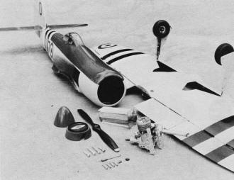
Tank is shimmed up or down by sheet balsa for
engine run adjustment. This picture illustrates ease of repair and
adjustment of major components and breakdown for shipping.
Actual construction of the Sea Fury was at best tedious, laborious,
and difficult, with its molds, jigs, mockups, and machining. I was
shooting for a final weight in the low 60 oz. range and was more
than a little unhappy when I realized it was going to be impossible.
Where did I go wrong? Hadn't I done all the necessary molding, sanding,
and constructing of built-up assemblies? Well, yes, but as I looked
at the finished Sea Fury sitting in all of its pristine beauty atop
my coffee table (by now my workbench was too small), it hit me.
Somewhere between the initial concept and the designing of the fuselage,
it had gotten away from me. Despite its short 60 in. wing, my Sea
Fury was definitely not a Bearcat sized airplane.
I think the day I first flew the Sea Fury was perhaps the most
pleasurable day that I have ever spent in modeling. When the airplane
was ready, I picked a perfect spring day for the Sea Fury's initial
flights. My wife, Linda, packed a picnic lunch while I loaded the
car with two large cardboard cartons of miscellaneous spare parts,
tools, camera equipment, etc. We set forth tor a site in West Fort
Worth, 35 miles away, where beautiful, smooth circles lay in a quiet,
wooded, park-like atmosphere. After arriving, we first photographed
the Sea Fury in both color and black and white (just in case). After
running out the new 65 ft. .018 control lines, we pull-tested the
airplane and lines, and were ready to fly.
What a thrill that first flight was! The sight of a Sea Fury
out there on the end of the lines was terrific! Line tension, however,
was only fair and seemed to disappear during maneuvering flight.
The controls were so sluggish that round loops were difficult. When
the engine cut, the glide was good and the Sea Fury settled gently
onto its shock absorbing gear to end a highly satisfac-tory first
flight.
I called to Linda for a sandwich and a Coke while I removed the
wing. To correct the sluggishness of control, I changed the flap-elevator
ratio from 30° flap - 30° elevator to 30° flap - 45°
elevator, and added 1/2 oz. of tip weight to improve line tension.
On its second flight the Sea Fury was. very responsive to control.
Line tension, while improved, was still insufficient and it turned
tighter inside than outside, To balance inside and outside turn
rates, I removed the wing again to adjust the elevators downward
slightly with neutral flap and more tip weight was added to further
improve tension.
On the third flight the Sea Fury turned well, both inside and
outside, and the general improvement in flying characteristics permitted
closer evaluation of specific areas which needed improvement. For
example, it was very light on the lines overhead and now that I
had time to look, the Sea Fury was flying banked into the circle
both upright and inverted. So that's why I had so little line tension!
The Sea Fury was my first airplane built with exactly equal span
inboard and outboard wing panels and the extra lift of the faster
outboard wing was causing it to fly banked into the circle. While
I had anticipated a need for adjustable tip weight, I was surprised
at the bank angle and a little unhappy when I saw that the tip weight
box wasn't big enough. That first night I had to settle for taping
extra weight onto the outside of the outboard wing tip.
To adjust the tip weight, I added 1/2 oz. onto the tip each flight.
With each addition of tip weight, the airplane flew flatter and
line tension improved until, at three oz. total tip weight, the
Sea Fury started "hinging" in the squares. With a reduction of 1/2
oz. of tip weight, the tendency to "hinge" was gone and the Sea
Fury flew flat with good tension.
To improve the overhead tension, I moved the leadouts forward
three times, in 1/4 in. increments until no further improvement
in tension was noted and the Sea Fury was beginning to feel "doggy."
Moving the leadouts back one 1/4 in. increment resulted in nearly
optimum leadout location.
By this time it was beginning to get dark and time remained for
only one final evaluation flight. This would be a full pattern flown
at five feet except for the triangle and hourglass bottoms where
I would pull out high and extra tight to evaluate the turning (lifting)
capability. The Sea Fury flew beautifully except for a noticeable
stalling tendency in the lower right triangle and hourglass corners.
Well, I thought, you can't have everything, and all things considered,
I was pretty proud of my 71 oz. airplane at this point.
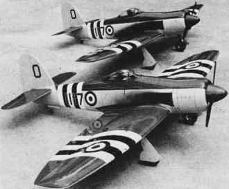
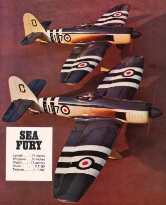
Two spectacular models of the Sea Fury.
That night I thought about the stalling tendency and decided
that it might be improved if I could only hang the flaps out a little
farther for more lift in the corners. To accomplish this, I changed
the flap-elevator ratio to 30° flap-37° elevator. The change
of ratio would definitely use more flap for any given rate of turn,
but the extra flap would also reduce the effectiveness of the elevators
making the airplane appear to turn sluggishly again. To compensate
for the aerodynamically reduced sensitivity, I modified my small
E-Z-Just handle for wider line spacing by cutting the plastic, moving
the lines to the extreme top and bottom of the handle, and epoxying
small pieces of plywood into the slots under the relocated lines.
The next day's flying proved the combination of ratio change and
handle modification did reduce the stalling tendency to the point
that the triangle and hourglass corners could be tightened normally
with no sign of buffet and no apparent change of sensitivity.
When I tried flying the Sea Fury with its spinner, I found that
it ran smooth and true but the nose cap would fly off each time
the engine stopped. It seemed the precessional effects of high pitch
rates were flexing the spinner backplate along the propeller axis
where the backplate was weakened by the prop blade cutouts. This
flexing would loosen the nose cap. After stiffening the backplate
with a fitting machined by Bob Wilder, the problem was completely
cured. In fact, considering spinner vibration problems that I have
had on smaller airplanes, I am amazed at the rather unbelievable
smoothness of this very large spinner. (This flexing has since been
corrected by Williams.)
To summarize the Sea Fury's flying characteristics at this point,
overall I thought it flew very well and was definitely competitive.
It turned as well as my Bearcat, but felt and looked much smoother
due to the increased tail moment. Line tension was good except for
the top of the vertical eight in wind over 12 knots. In a strong
wind I would occasionally run out of elevator in the vertical eight
as I started down from overhead. Also, the shock gear seemed to
cause bouncy landings but that turned out to be a simple matter
of improper location. Bending the gear back slightly fixed the landings
completely.
Finally, however exciting, the Sea Fury was difficult to fly.
It could fly any maneuver competitively, but only nine out of ten
times. I found that no matter how much I practiced, I would usually
bounce a corner or miss a pullout or an intersection on nearly every
flight. Still, if I could put it together at the Nats, the combination
of smooth corners, good shapes and impressive appearance could very
well win.
At the '71 Nats, neither my flying or the Sea Fury's appearance
seemed to make much impression on the judges in the first round
of finals. I wound up "in the pack" in the mid 440s. I n the second
round, the Sea Fury nosed over on takeoff after being released down-wind
in a strong, gusty wind condition. All right, so an honest conventional
gear is still a competitive disadvantage, even with shocks. A month
later, I found this type of takeoff accident could be prevented
by launching into the wind. A 73 oz. airplane seldom becomes airborne
accidentally.
I think most Nats stunt fliers were impressed by Gene Schaffer
and his "Stunt Machine" performing in the wind. Gene's pattern seemed
typical New York style except for his rather blinding corners. Chuck
Hora thought Gene's corners looked as though the airplane had been
"nailed," then "swiveled." While I also thought Gene's corners were
unnecessarily tight, they were impressive and attention-gathering
in their own right, and like beauty or semi-scale, served to attract
the attention of the judges for "out of the pack" scores. I went
home with the realization that the Sea Fury's corners should be
further improved before Cleveland's FAI Finals to improve my chances
of making the FAI team.
As a matter of fact, I had two problems to overcome. First, the
Sea Fury left a heavy smoke trail which distracted the judged by
drifting in the rounds and being blown to the ground by the flaps
in the bottoms of the squares. This caused the Sea Fury to appear
to bobble when, in fact, it hadn't. Since the ST 60 would tolerate
much less oil than Superfuel's 29%, I mixed my own brew: 5% nitro,
20% Ucon oil, and 75% methanol. The smoke problem was cured, but
the extra 9% combustibles increased the engine run from 6:15 to
7:00 which resulted in overruns in the FAI pattern. I decreased
the run by enlarging the venturi from .305 to .315 ID. Burning the
extra 9% combustibles in 6:15 instead of 7:00 released extra power
from the engine which "perked up" the Sea Fury's performance all
around.
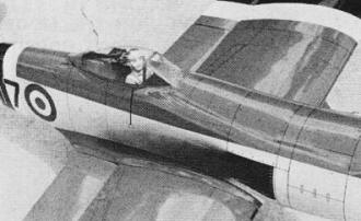
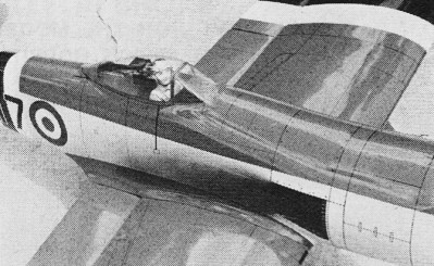
You'd look away too if you saw the ground so
close, so often. Note rivet detail; simple, clean cockpit.
Second, I began retrimming. I wanted to increase the crispness
of my maneuvers by tightening all of the corners somewhat. To accomplish
this, I added nose weight, knowing that more stability would result
from a more forward CG location. Now more control deflection would
be required to maneuver. The extra flap deflection increased lift
again permitting sharper corners and a trouble-free vertical eight.
Admittedly, it also took more deflection of the handle too, but
I soon became used to it. The extra stability from the increased
nose weight also cured the Sea Fury of being difficult to fly. It
no longer had a mind of its own. It drove smooth and tight to crisp,
accurate corners. At last the Sea Fury had arrived as an unlimited
competition stunt ship. Five flights on that snarling, pulling,
groovy son of a gun would spoil for anyone, forever, the put-put
of a Fox 35.
On the day I was to leave for the FAI Finals, I ran out of fuel
in cloverleaf on my last practice flight. Rather than accept a safe
inverted landing with minimal damage, I "went for broke" again and
tried to whip it through to save the airplane, undamaged, for Cleveland.
It didn't work. Looking down at the mess, I knew my "go for broke"
year had ended.
As far as I was concerned, the Sea Fury had proven itself a competition
stunt ship even though it had never won a contest. Excepting Bob
McKinney, no one had seen it fly well. Rather than let it end there,
I decided to rebuild the old Sea Fury and to start immediately on
a new Sea Fury incorporating improvements based upon experience
gained from 303 flights on the original.
First, ground handling could be improved by shortening the landing
gear a little to provide a flatter sitting attitude. The old gear
had turned out over scale length anyway. Shortening the main gear
1/2 in. would actually improve upon scaleness. I would, of course,
retain the shock absorbers as the guaranteed landings and visual
effect were certainly worth the small extra weight.
Second, it seemed that slightly larger stabilizer and elevators
would further improve the Sea Fury's "groove." Also, the larger
elevators should allow changing the flap-elevator ratio of 30°
flap-37° elevator used on the Sea Fury I, to 30° flap-30°
elevator, thereby wringing more lift from the wing's available area.
This would permit still tighter corners.
While designing the new stabilizer, it seemed a good idea to
incorporate some "direct lift." "Direct lift" is simply rendering
the elevators aerodynamically ineffective or insensitive around
neutral. With "direct lift," small control handle inputs have little
or no effect at the elevators but the accompanying small movements
of the flaps cause the airplane to rise or descend smoothly, without
any change of pitch attitude. By making most small flight path adjustments
with the flaps only, the apparent smoothness of the flight is greatly
improved.
There are several easy methods of obtaining "direct lift." The
first, and most common, is simply to drill out the elevator pushrod
bushing in the elevator horn to put "slop" in the elevators. Most
fliers who use "slop" can move their elevators up or down about
3/16 in. at the trailing edge without moving the flaps, or, more
properly, can move the flaps without moving the elevators. Another
method used by World Champion Bill Werwage on his "Pacemaker" is
to make the stab thicker than the elevators. Also, at one time or
another, RC fliers Phil Kraft, Jim Kirkland and Art Schroeder have
related their experi-ences with stab types and generally agree that
an airfoiled stab arrangement will have less elevator sensitivity
around neutral than a flat stab setup. Since I practice 800 to 1000
flights each year, I already have problems enough with wear, so
I decided to avoid "slop" and combine Bill's thick stab with as
much airfoil as my construction method permits to obtain "direct
lift" characteristics for the Sea Fury II.
Third, just in case the ratio change for increased lift was not
quite enough by itself to obtain really outstanding corners, I would
add one in. of span to each wing panel for a 4% increase in wing
area.
Finally, I would try again to reduce weight, particularly in
the tail. Because of the Sea Fury's unusual moments, a fraction
of an oz. saved in the tail would be greatly magnified in the reduction
of nose weight required. For example, the wing fillets were already
molded from 1/16 in. sheet balsa but the Epoxolite fillets at the
fin, stab arid. fuselage junction could be replaced with 1/32 in.
balsa sheet fillets. A plastic hub Williams tail-wheel would replace
the metal hub Perfect. Additional weight savings could be realized
by skeletonizing the main gear platforms and spar webs. In addition
to the normal hollowing of the wing tips and cowl ring, the rudder
and elevator spars were hollowed as were the specially cut wing
trailing edge pieces. I'm sure you get the idea. In fact the Sea
Fury II did weigh nearly two oz. less than the Sea Fury I. I had
hoped for a greater savings. It looks like the larger wing and stab
offset most of my additional effort.
The new Sea Fury and repairs to the old were were begun simultaneously.
The Sea Fury I needed a completely new forward fuselage assembly
beginning just ahead of the cockpit. Molding the new fuselage half-shells
fitted nicely with the molding of the new "II" fuselage shells and
much time was saved by constructing duplicate bulkheads, firewalls,
tank compartments, cooling air bypasses, cowl rings, etc. By the
time the Sea Fury I's structure was repaired, the basic fuselage
for the Sea Fury II was complete.
I'm certainly glad that I repaired the broken Sea Fury because
work progressed slowly on Sea Fury II due mainly, I guess, to watching
too much TV in my workshop. By the time I finished Sea Fury II on
July 4th, I had been able to put in nearly 300 practice flights
and two contest wins on the repaired Sea Fury I. Also, the repaired
Sea Fury was used to break in several new and overhauled engines
and at least 100 flights were made using Sea Fury II's tank, engine
mounts, and muffler before Sea Fury II was finished.
The first flights on the new Sea Fury II eliminated any doubts
about the value of my modifications for improved performance. The
most noticeable difference was the Sea Fury II's ability to turn
in the lower right triangle and hourglass comers. With the Sea Fury
II there is no buffeting in those corners no matter how hard you
tilt them. Corner radius everywhere is now limited only by reaction
time, smoothness and practice. The new Sea Fury II is so much improved
over the Sea Fury I that my next building project is larger stab
and elevators for the old Sea Fury to improve its "groove" and permit
the ratio change for more lift. If this doesn't produce approximately
identical performance to the Sea Fury II, I'll build a new wing
with the extra two-in. span. The Sea Furys will then be structurally
identically. A rework of the cockpit and anew paint job will complete
the transformation.
My final change to improve the overall appearance of the Sea
Fury's pattern was to increase the control-line length from 65 ft.
to 70 ft. People have remarked before that a large airplane like
the Sea Fury tends to look cramped for space while maneuvering on
my old lines. With the new, longer lines this cramped appearance
was completely eliminated. Now people complain about the size of
my maneuvers. Anyway, the net effect was definitely beneficial so
the Sea Fury II was trimmed to fly best on the longer lines.
I did notice one curious effect of flying on longer lines. To
maintain the necessary five sec. lap time for a 6:30 pattern, I
had to lean the engine slightly. The leaner mixture brought unexpected
fuel economy and my engine run went up to 8:00. Further enlarging
the venturi led to instability of my run, so instead, I shortened
the duration to 6:30 by increasing the nitro content of my fuel
to 10%.
By working a less desirable schedule and losing a lot of sleep
to early morning practice, I was able to get 150 flights on the
Sea Fury II before leaving for the 1972 Nats in Chicago and another
45 flights in Chicago before Open finals. With a good airplane and
a luck draw in flying order, my Sea Fury and I were able to pull
off a win in Open Stunt. This was particularly satisfying as a few
short years ago separate Stunt events were sometimes held for semi-scale
stunt ships because of their supposed inability to compete effectively
with "classic" stunt ships, This year, realistic semi-scale stunt
ships took first, third and fourth in Open Stunt and first in Senior
Stunt. Maybe now I've heard the last of those cracks about semi-stunt
scale ships.
Let me end with a precaution. It has been demonstrated that realistic
semi-scale airplanes can compete effectively with classic stunters,
but - they are heavily compromised. With less than optimum moments,
shapes and wing locations, and with a significant tendency to build
overweight because of greater bulk and larger surface areas to paint,
you start out with two strikes against you in competition. Add to
the a requirement for up to three times greater construction time,
and it becomes obvious that realistic semi-scale projects should
not be lightly undertaken. To design a realistic semi-scale stunt
ship you must somehow overcome its disadvantages in layout and bulk.
To do this you will surely need to use unique construction techniques,
extra built-in trimming capability, up-to-date aerodynamics and
clever or creative ideas and concepts. If you are clever or lucky
enough to come up with a truly competitive design, you still have
to practice as much as the other top fliers to develop the necessary
flying skills to win. In other words, think about it.
Notice:
The AMA Plans Service offers a
full-size version of many of the plans show here at a very reasonable cost. They
will scale the plans any size for you. It is always best to buy printed plans because
my scanner versions often have distortions that can cause parts to fit poorly. Purchasing
plans also help to support the operation of the
Academy of Model Aeronautics - the #1
advocate for model aviation throughout the world. If the AMA no longer has this
plan on file, I will be glad to send you my higher resolution version.
Try my Scale Calculator for
Model Airplane Plans.
Posted June 6, 2015
|