|
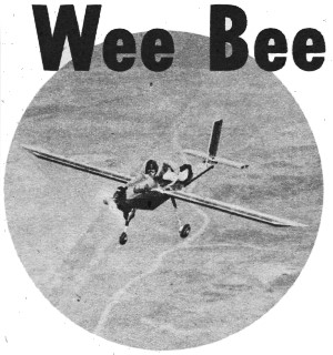
The
Wee Bee
was at one time considered the world's smallest man-carrying aircraft. It had an
18-foot wingspan and weighted 215 pounds without pilot. Lloyd Hunt's model of the Wee
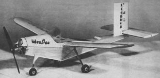
Bee is designed for either free flight or control line. For C/L it is powered by an
.049 engine, and for F/F it uses an .020 engine. Its 22" wingspan makes it about
1/10th scale. Construction is built-up fuselage, wing, and tail surfaces with balsa
sheeting over all. If you are looking for an unusual scale model that will not
require a lot of detail to make it look authentic, the Wee Bee would make a good
subject.
Wee Bee Article & Plans
By Lloyd V. Hunt
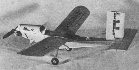
World's smallest man-carrying plane looks like a
big model; makes a swell free flight or U-C scaler.
The Wee Bee, one of the world's smallest airplanes, first hopped for the newsreels
in December 1948. Shortly after its first real
 flight to altitude it was taken to London,
England; to appear in the International Air Pageant. In London, the little airplane was
flown before 90,000 people attending the gigantic air show. A week later it went to Belfast
in Ireland to appear in the Royal Air Force pageant there. On its return home, it stopped
at the National Air Races in this country where it made a flight before another huge
crowd of spectators. flight to altitude it was taken to London,
England; to appear in the International Air Pageant. In London, the little airplane was
flown before 90,000 people attending the gigantic air show. A week later it went to Belfast
in Ireland to appear in the Royal Air Force pageant there. On its return home, it stopped
at the National Air Races in this country where it made a flight before another huge
crowd of spectators.
Since the initial hop over a year ago, and since its return to San Diego from Europe,
a number of major improvements have been incorporated in the airplane. Wing tips have
been added, a new spring landing gear replaces the older one, a larger windshield, cowling
and other changes have really improved the little ship. The Wee Bee is powered with a
30 hp 2-cylinder horizontally opposed engine. Its weights are: empty 215 lbs., useful
load 200 lbs., gross weight 415 lbs. Cruising speed is 70 mph at level flight, stalling
speed with power off, 45 mph. Take-off ground run is 550 feet, and landing ground run
300 feet.
Construction is all-metal. The wingspan is 18 feet and the fuselage is 14 feet long.
Landing gear is of the fixed tricycle type, equipped with hydraulic brakes. The nose
wheel is steerable.
Ken S. Coward, an aeronautical engineer who is employed in flight research at Consolidated-Vultee,
designed the airplane. Others associated with the development of the Wee Bee are Bill
Chana, who is currently flying it, Karl Montijo who conducted the early flights and piloted
the airplane in the European Air Shows, and James Wilder, a mechanical engineer, who
performed the powerplant installation work.
 The
author wishes to express his thanks to Mr. K. S. Coward for his cooperation in furnishing
drawings, photos, and data which made the exact reproduction possible. The
author wishes to express his thanks to Mr. K. S. Coward for his cooperation in furnishing
drawings, photos, and data which made the exact reproduction possible.
Several things should be pointed out before construction is begun. Your workmanship
must be light, for 3-1/4 to 3-1/2 ounces maximum is about tops for the Infant-powered
version. All the wood is coated with a mixture of clear dope and castor oil; use a half
teaspoon of oil to two ounces of dope. The oil will prevent brittleness and hence retard
splintering which is the drawback to sheet balsa design and construction. The one-side
mounting of the engine preserves the scale effect of the cowl line and in fact gives
better results. In the event that your Infant will not start in this position, be sure
to check the fuel line first to see that there is not an air space in the line.
Our model is presented as a control line flyer or a free flight. The power used for
the control line model may be either the Torp Jr. or O.K. Cub .049 or .074. The latter
can be installed with only minor modifications; for the free flight version use the K&B
Infant engine.
Construction is identical in both types, but with a few minor changes for the free
flight model, such as added dihedral and larger tail surfaces to insure stability.
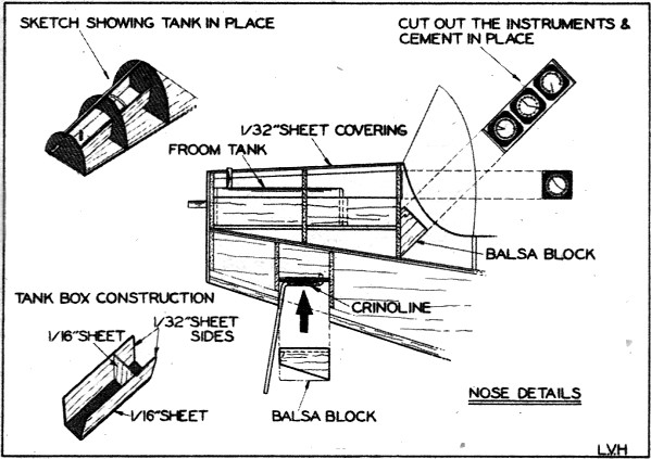
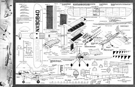
As for construction, let's first consider the fuselage. Sketches indicate the extreme
simplicity of the fuselage assembly. Select a firm piece of 3/32" sheet balsa for the
basic fuselage keel, lettered A. This template is indicated by the heavy lines of the
part in the lower right-hand corner of the drawing. Next cut out the fuselage formers
from hard 1/16" sheet and cement them to the fuselage keel as shown in the sketch. While
these parts are drying, cut also from 1/16" sheet balsa and cement in place templates
B, C. D. (In template D cut out the rudder slot location for whichever version you are
building). Then cut from 1/16" sheet balsa and cement to template B formers E, F, G.
(You will note that they extend over template B.) The reason is, when covering these
formers with 1/32" sheet balsa, it will form the outer flange of the cowl.
If you are building the control line model, former F should be cut out to allow gluing
in the control line tank. Cement in place three 3/32" sq. hard balsa stringers for the
cowl construction. Use only one 3/32" sq. stringer for the control line cowl.
Next, glue in place the piece marked I to the fuselage keel. This part is the main
landing gear platform. As the last step before covering the fuselage sides with 1/32"
sheet balsa, bevel the bottom of template A to a sharp point to facilitate covering the
sides. You are now ready to cover the sides of the fuselage. Starting at former No.1
and working back to the middle of former No.5, cover both sides of the fuselage. Then,
working from the middle of former No. 5 to former No. 14, cover in the same manner. Locate
and cut out the landing gear slots, both nose and main gear. See sketch.
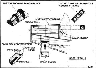 Covering
the cowl is accomplished by cutting from 1/32" sheet balsa the two cowl templates, making
sure first to dampen them lightly, and cement in place. Hold the templates in place with
pins while they are drying. To finish the cowl detail cement the two 1/32" sheet pieces
marked J in their exact location. After this, P1, P2, P3 are glued in place, on the sides
of the fuselage. Now add the following details: a strip of 1/32" x 1/8" sheet balsa along
the entire length of the bottom of the fuselage, leaving open the aforementioned nose
gear slot; two strips of 1/32" x 1/8" x 6 1/2" sheet balsa to the sides, as noted in
the sketch, to form the simulated aluminum flange. Covering
the cowl is accomplished by cutting from 1/32" sheet balsa the two cowl templates, making
sure first to dampen them lightly, and cement in place. Hold the templates in place with
pins while they are drying. To finish the cowl detail cement the two 1/32" sheet pieces
marked J in their exact location. After this, P1, P2, P3 are glued in place, on the sides
of the fuselage. Now add the following details: a strip of 1/32" x 1/8" sheet balsa along
the entire length of the bottom of the fuselage, leaving open the aforementioned nose
gear slot; two strips of 1/32" x 1/8" x 6 1/2" sheet balsa to the sides, as noted in
the sketch, to form the simulated aluminum flange.
Form the main spring landing gear from 32ST Dural, and not from soft aluminum sheet,
by laying it out on a strip of 1/4" x 6 5/16" in length. Bend to shape and cement to
the landing gear platform marked I. Two strips of 1/8" x 1/4" x 1 13/16" sheet balsa
are used as a fill-in, employing the sandwich method to hold the gear securely. The nose
gear strut is bent from 1/16" dia. wire. Next, bend and form the nose-wheel yokes from
.046 dia. wire. (Two required.) The nose wheel is attached to the yoke by first inserting
one side and then the other; join the yokes to the 1/16" dia. wire strut with copper
wire and solder.
This assembly is then wrapped to the 1/16" sheet plywood platform marked H, with crinoline,
and cemented generously. When dry, place it in the nose gear slot; next fill in with
a small block of balsa, sanding to shape to complete. The nose gear details may now be
added. These consist of pieces marked L1, L2, L3. L1 is formed of two strips of 3/16"
square balsa. Cement them to the landing gear strut, and sand to a round shape as shown.
Just a word of caution. Do not cement this part to the bottom of the fuselage as the
nose gear will need a slight play to absorb the shock of landing. This will also apply
to L3 which is cemented to L1. Lastly, glue L2 to the fuselage.
To finish the fuselage, cement in place the 1/16". sheet plywood motor mount. Mount
the K&B Infant engine with two small wood screws. Add the 1/32" engine cowling. Lastly
glue in place the pieces C1 and C2 which are cut from 1/32" sheet balsa. (Two of each
are required.)
Now, let's get back to the main spring landing gear. If you are building the control
line model, use the standard rubber wheels. For the brake drum detail use two aluminum
hubs from a pair of rubber wheels and fill in each hub with a 1/32" sheet balsa strip.
Bolt the wheels on the spring gear as shown. If you are building the free flight version,
we would suggest making balsa wood wheels to keep down the weight.
The next step in construction is to build the wing which is made in one piece for
the control line version. Begin by cutting out the bottom wing template from 1/16" x
3" x 22 1/8" sheet .balsa. This is the projected length of the wing template, as the
added 1/8''' on the bottom wing template will be utilized in forming the wing tips. One
important point in both versions is that the undersurface of the wing template is purposely
cracked at the last rib location near the tip to form the wing tip. Block up the wing
tip 7/16", cement. Now after adding the 1/8" sq. leading edge strip, follow up by beveling
the trailing edge to form a joint with the 1/32" top sheet covering. Cut and cement in
place the wing ribs, the center rib being cut from 1/8" sheet and the remaining eight
from 1/16" sheet.
 Next, cement the bell crank mount to the bottom of the
wing template and insert the bellcrank pivot bolt. Add the bellcrank to the opposing
side of the wing template and lock with two nuts. Glue in place the three 3/32" spars.
and finish the wing by covering the top with two pieces of 1/32" sheet. Last of all add
the line guides at their respective locations. Next, cement the bell crank mount to the bottom of the
wing template and insert the bellcrank pivot bolt. Add the bellcrank to the opposing
side of the wing template and lock with two nuts. Glue in place the three 3/32" spars.
and finish the wing by covering the top with two pieces of 1/32" sheet. Last of all add
the line guides at their respective locations.
The free flight wing is built almost in the same manner as the control line wing,
except that the 1/16" sheet bottom wing template is cut apart on the center line to allow
for adding dihedral. Before starting construction, cut ten ribs from 1/16". sheet. Be
sure to cut out the slot in the two center ribs to allow for the wing joiner to be glued
in place. Then, cut the wing joiner from hard 1/8" sheet balsa. Next, add the 1/8" sq.
leading edge strip and the five ribs to the one panel; also, cement the wing joiner in
place at this time. Now cement to the ribs the three 3/32" sq. spars. Finish by covering
the panel with a 1/32" sheet balsa covering, Build the other panel in the same manner
as the first. Finish by adding the correct dihedral by blocking up the tip to one inch
and cementing together.
Construction of the pilot bed is started first by cutting from 1/8" sheet the two
pieces marked A. Cement on to the wing in their correct location. When dry, fill in between
these parts with a piece of 1/16" sheet balsa 1 3/4" x 2 3/32" long. Next add the piece
shown in the sketch of the pilot bed which is a strip 1/16" x 2" long to the parts marked
A. This forms a base to glue the bed detail to the end of the 1/32" cowl. For the free
flight wing, pieces marked A will have to be trimmed slightly around the wing contour
to allow for the dihedral in the wing. Now the wing may be cemented in place onto the
fuselage. To finish the pilot bed detail, cut the two pieces marked B from 1/16" sheet.
These pieces are to be added last, as they form, not only the remaining pilot bed construction,
but also the slight wing fillet which may be seen in the top view of the drawing. Also
fill in between these parts with 1/16" sheet balsa and the 1/16" sq. strip to complete.
The horizontal tail surface should be built now and the control system assembled.
Cut the stabilizer from 3/16" sheet, carve and sand to a streamlined section. Leave a
flat surface on the center of the bottom of the stabilizer for later assembly to fuselage.
The elevator can also be cut from 3/16" sheet balsa. Carve and sand to the remaining
streamline section. Cut a slot on the center line of the elevator just far enough into
it to allow for inserting and cementing m place the control horn which is cut to outline
from 1/32" brass sheet as shown in the detail.
Let this piece dry. and meanwhile bend from wire the pins that fit into the 1/16"
dia. aluminum tubing which should be added at this time. The tubing runs the entire length
of the elevator. This assembly should be cemented firmly along with a strip of silk to
hold it in place. Next add the 1/32" dia. wire control rod between the bellcrank and
control horn. We've found this arrangement to be successful, but you may install your
own system. Cement the stabilizer to the fuselage (zero incidence).
Cut the control line model rudder also 'from 3/16" sheet, carving and sanding to a
streamline shape and offsetting it 3/8" to the outside of the circle. Then, cement the
rudder to the scale location (into template D).
The free flight stabilizer and rudder are constructed from 1/32" sheet balsa templates
incorporating the use of three spars instead of ribs. Cut out the two stabilizer patterns,
and bevel the trailing edges of each pattern by sanding lightly to make a joint for cementing
the patterns together in forming the stabilizer. Next add the 1/8" sq. leading edge to
both patterns; then add the 1/16" sheet spars Nos. 1 and 2. Lastly add spar No. 3 and
cement the patterns together to form the trailing edge.
Add the two 1/16" sheet tips to finish the stabilizer. Construct the rudder in the
same manner as the stabilizer, adding the 1/16" sheet tip and the bottom 1/16" sheet
cap. Cement the assembled rudder into the free flight rudder slot location. Before cementing
the free flight stabilizer onto the fuselage, cut a small wedge to be used as an incidence
guide for the free flight stabilizer setting. This wedge should be cut to form a 1/8"
negative incidence setting. This completed, cement the stabilizer into position.
Finally, sand the entire model to remove any imperfections and fuzz. End the construction
by adding the rudder pedals (two) which are cut from 1/32" sheet balsa and cemented to
the fuselage at their location.
Finishing details for the control line model are as follows. Paint the entire ship
aluminum, which can best be applied by spraying or may be thinned and applied with a
brush; add wing numbers and rudder numbers cut from black Trim Film, or laid out first
in pencil outline and then filled-in with black India ink. Adding the brake-drum line
detail is optional, but this may be constructed by bending to shape from wire winding
as shown on the spring gear. The flags on the rudder (we cut them from different colors
of Trim Film, but these may be painted on) are, starting from the top, the United States
flag, the one representing the Belfast, Ireland, Royal Air Force Pageant, and lastly
the flag representing the International Air Pageant in London.
Add the control surfaces, outlined with Trim Film or by ruling in with black India
ink. Cut from celluloid and cement into position the windshield. If you wish, the name
Wee Bee may be added to both sides of the cowling filled in with red and trimmed with
black.
Details for the free flight version are the same as for the control line model, but
in order to keep the weight at a minimum, omit painting the model aluminum.
Balance the control line model where indicated. Fifteen foot lines may be used to
find out the characteristics of your ship. Be sure to guard against over-controlling
during the first flights as you will find that the Wee Bee will almost fly itself. We
used a Kay Sun propeller for best results.
For the free flight ship, balance at its respective location, glide the ship over
tall grass. After you have obtained a flat glide start the K&B engine using no more
than three-quarter power. Launch with a slight push. For power adjustments a slight downthrust
might be necessary.
Bill of Materials - Wee Bee
3 pieces 3/32" sq. x 36" hard, stringers. 2 sheets 1/16" x 3" x 36", templates, formers,
wing ribs, spars, etc. 2 sheets 1/32'" x 3" x 36", templates, wing covering, cowing,
details. 1 1/8" x 3" x 36," pilot bed details, etc. 1 pc 1/16" x 1 1/2" x 3" plywood,
firewall. 1 pc 1/16" x 3/8" x 2 1/16" plywood, bellcrank mount. 1 pc 1/16" x 13/16" x
13/16" plywood, landing gear platform. 1 pc 1/16" dia. wire 2 7/8" the nose gear strut.
1 pc .046 wire 2 1/2" long, landing gear yoke. 1 pc Dural aluminum 1/4" x 6 7/8" spring
gear. 1 pc 1/16" x 6 1/4" dia. aluminum tubing for control line hinge, wire for pins
to fit inside the tubing.
1 strip silk 6 1/4" long. 1 pc brass 3/8" x 5/8," control horn. 1 pc 1/32" x 3/8"
x 1 3/4" aluminum, bellcrank. .040 piano wire, control line guide. 12" 1/32" dia. wire,
control rod. Two 4-40 bolts for spring landing gear. Three wheels, two of 1"dia., 1 of
3/4" dia.
Cement, silver dope, fuel proofer, Trim-Film, black India Ink, sandpaper, .020 free
flight engine, .035-.049-.074 control line engine, small gas tank celluloid, accessories.
Photo Credit List
Page 12 - Warren Watson.
Page 23 - H. G. Martin.
Page 26 - Heron: H. Levy.
Page 27 - Flying Wing: Hans Groenhof; Meteor NF. 11; British Office of Information;
Kabru 48; H. Levy; Finnmark: H. Levy.
Pages 34-35-36-37-38-H. A. Thomas, S. Calhoun Smith, D. David Bash, A. L. Lewis.
Page 40 - Plymouth.
Page 44 - Plymouth.
Wee Bee Control Line Airplane Plans
Notice:
The AMA Plans Service offers a
full-size version of many of the plans show here at a very reasonable cost. They
will scale the plans any size for you. It is always best to buy printed plans because
my scanner versions often have distortions that can cause parts to fit poorly. Purchasing
plans also help to support the operation of the
Academy of Model Aeronautics - the #1
advocate for model aviation throughout the world. If the AMA no longer has this
plan on file, I will be glad to send you my higher resolution version.
Try my Scale Calculator for
Model Airplane Plans.
Posted October 13, 2018
|