|
Dr. Ralph Brooke was a member
of the 1963 U.S. International Team, which won the World Champion ships at Genk, Belgium.
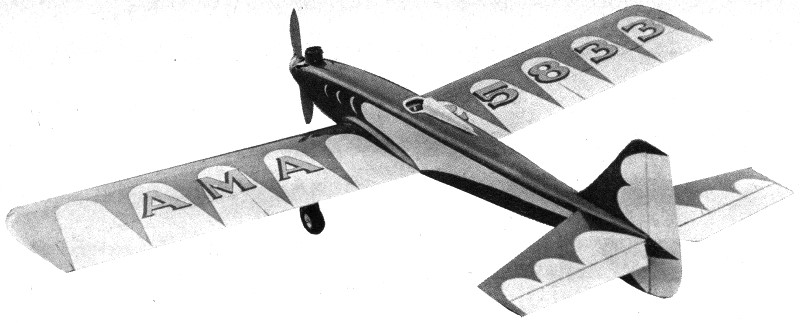
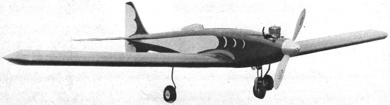
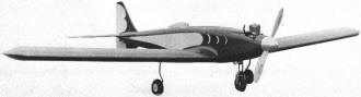
His custom designed "Whistler" full house radio control model airplane is featured in
this 1963 issue of American Modeler magazine. The engine was a Veco .45,
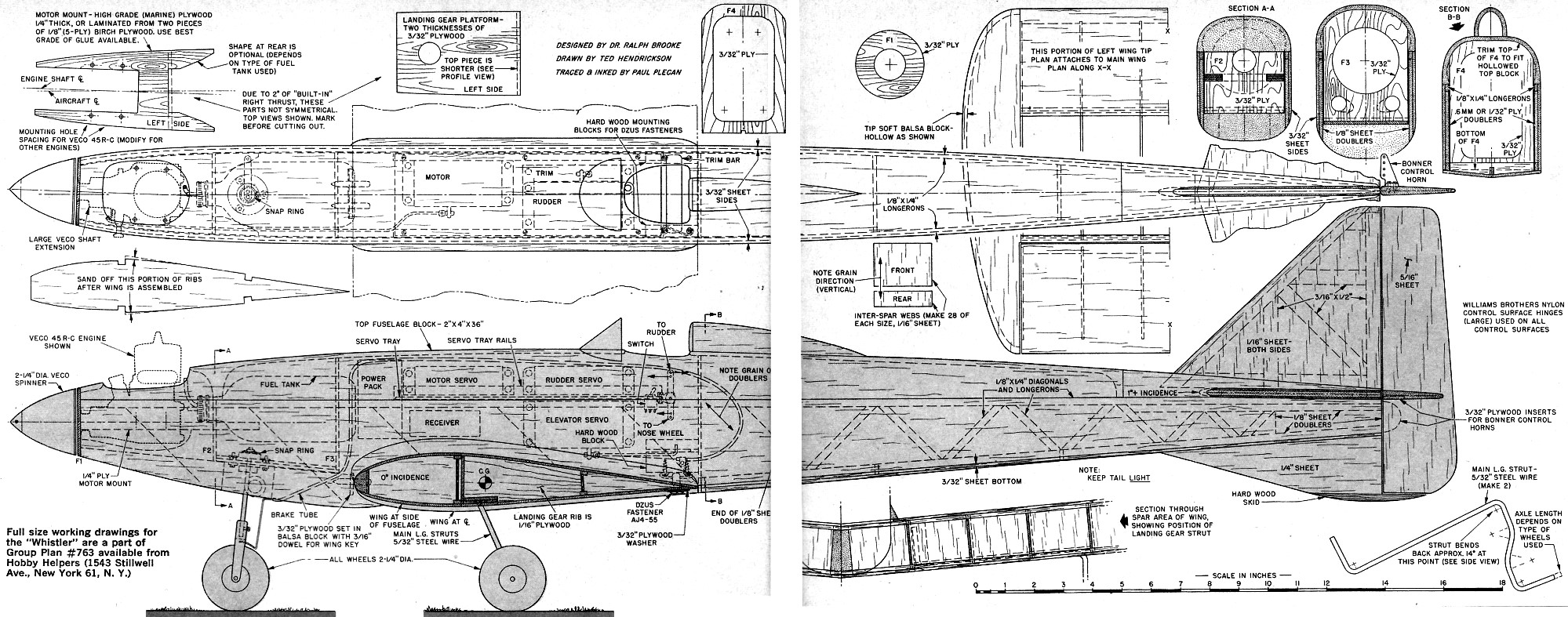
which was smaller than the .60 size used by many competitors of the day. The plans
are well-drawn, but the wing portion is broken across the two sheets, and only the
left half is shown. The wingspan is only 59", so it really wouldn't have been that
much trouble to put at least the entire wing half on one sheet. That has always been
a pet peeve of mine. Otherwise, the Whistler is a nice looking model and could easily
be adapted to electric power.
Dr. Ralph Brooke's "Whistler" Article & Plans
Dr. Brooke is a Seattle, Wash., dentist, ex-USAF'er, graduate of Univ.
of Wash.
Newest member of America's International Radio Control Competition team brings you
his famed Multi Class aerobatic aircraft, reveals design secrets that can be of very
great help to all would-be R/C flyers. Balsa importers should be happy, too!
While searching for a smooth-flying, stable multi R/C model, I experimented with a
number of different designs, the latest and best being "Whistler". Inspiration came from
a design of Milt Boone's which I built a year ago. During several long bull sessions,
Milt sketched out what he considered to be the "ideal" multi design, which I proceeded
to build. The distinguishing feature of this model was that the wing was set up deep
into the bottom of the fuselage, approaching true mid-wing conformation. This model showed
great promise, but unfortunately was short-lived (only one week!) due to an intermittent
power pack plug. (This same trouble also struck down the Whistler that I flew at the
'62 Nats.)
Construction of Milt's design was somewhat more difficult than the average multi job
and I could not quite muster up the courage for another "go" at it. His provided the
spark, however, and Whistler uses the same basic moments in its concept. A number of
unique design features distinguish Whistler from previous multi designs.
First, the wing has generous area (732 sq. in.) to give the model smooth low-speed
and aerobatic handling characteristics. The particular airfoil used is one by Glenn Spickler,
with a thick semi-symmetrical section and blunt leading edge for good low-speed characteristics.
Both a large vertical stabilizer and ventral fin are used to give smooth rolls. The ventral
fin provides a good distribution of tail area above and below the fuselage, and it also
helps to reduce corkscrewing in inside loops where the vertical stabilizer is less effective
due to wing wake.
 Large-chord, top-hinged ailerons are used to
give positive and snappy roll response, which is important in four-point rolls and other
similar maneuvers. There has been a trend lately toward full-span ailerons, the excuse
being that a stronger wing can be had, easier to build, etc. However, I find them mushy
in some flight conditions, making precise rolls more difficult. Large-chord, top-hinged ailerons are used to
give positive and snappy roll response, which is important in four-point rolls and other
similar maneuvers. There has been a trend lately toward full-span ailerons, the excuse
being that a stronger wing can be had, easier to build, etc. However, I find them mushy
in some flight conditions, making precise rolls more difficult.
The installation of the radio gear in Whistler was also inspired by Milt Boone (and
constructed by him to boot). Rudder, elevator, trim and throttle servos all mount on
a 1/16" epoxy printed circuit board, which is installed as a unit in the fuselage. The
servo wiring is all soldered to the board, eliminating the usual servo plugs, with their
48 flexing soldered connections.
Another innovation is the use of Dzus fasteners to hold the wing, rather than the
dowel and rubber band method. (Nowadays I really have to search high arid low in my tool
box for rubber bands to use in vibration checks!) Dzus fasteners give a very neat installation
and, contrary to popular opinion, the solid mounting of the wing prevents damage in cartwheels
and hard landings. In many dowel and rubber band set-ups, the stretched rubber bands
bite into leading and trailing edges, weakening the wing at the center section, where
"wing-folding" stresses are greatest! With the solid mounting the overloads are taken
up by the Dzus fasteners and dowels, which can be easily reinforced with plywood gussets.
 Whistler was designed to have quick but accurate
construction along with the best combinations of strength and light weight. Since the
plans are fairly well detailed most comments will deal with those points which differ
from usual practice. Whistler was designed to have quick but accurate
construction along with the best combinations of strength and light weight. Since the
plans are fairly well detailed most comments will deal with those points which differ
from usual practice.
In building the wing, the most important thing to have is a flat building board, 6
feet long and supported well enough to prevent warping. The thickness should approximate
3/4". A good grade of plywood will most often be your best bet in this department, as
the wing construction makes the difference between average performance and consistent
winning. A flat section is incorporated in the wing ribs to facilitate accurate construction.
I prefer templates of galvanized iron (aluminum is too soft). Note that two rib shapes
are needed. I rough-cut my ribs, employing two locator dowels through the stack to line
them up. Then a template at each side of the stack (dowel locator holes in same spots
as on ribs) and I'm ready to go at it with a long-bladed X-Acto knife. Don't overlook
the 3/4" center rib and the 1/4" false ribs. All ribs must be uniform. Trim the 3/32"
x 4" L.E. and T.E. sheets with the aid of a straight edge (a mighty important tool, often
overlooked by many hobbyists). Cement or glue the 1/8" x 1/4" spars in place.
Note the webbing used between the ribs and spars. Size must be exact on these, as
they act as rib spacers and must bridge the gap between spars. Note the vertical grain
direction. Construction should be proceeding quickly now, with the flat section (rear)
of the wing pinned to the work board and the front of the wing shimmed up. Ribs and web
pieces are cemented alternately in place, working from the center rib to the tips. Before
the top T.E. sheet is applied, be sure you have the aileron ribs in place. The aileron
is cut loose after the wing is completed and the cement has been allowed sufficient time
to dry well.
Note the filled-in area near the T.E. at wing center where the Dzus fasteners are
used. This area must be strong - you don't want the wing parting company with the model
in inverted flight! Bevel L.E. to match rib camber. I use two hacksaw blades bolted between
two pieces of 1/4" x 1/2" balsa to cut rib notches into leading edge stock. Adjust the
balsa blocks to limit the notch depth to 1/16". Scraps of 3/32" plywood across the L.E.
at the center section will reinforce the wing keying dowels. Bend bottom L.E. sheeting
up to meet L.E. and cement in place. Once the top sheeting has been completed, allow
the wing assembly to dry overnight so the cement will "set" completely before handling.
Accuracy is mandatory in the next step where we cut the wing in two and rejoin it
to incorporate dihedral. The first cut should be made on a circular saw to cut through
the center 3/4" rib at its center. Now set the saw for a 5 degree blade tilt. Chock up
the trailing edge so that the wing is about zero degrees incidence to saw table, then
make the dihedral cut. Plan your work and the procedure before making any cuts, as we
want a right and left matched set of panels to the wing. When viewed from above, try
to make dihedral cuts 90 degrees to L.E., so we do not incorporate sweep-back or sweep-forward
angles into the wing assembly. Butt-glue wing panels together, then cut through the center
section rib for the 3/32" plywood spar splice and aileron servo installation. Use a large
sanding block to round off the projecting sections of ribs aft of the main spar. Carve
and hollow the wing tips from soft balsa blocks. They should weigh 1/4 to 1/2 ounce when
finished. Carefully cut ailerons loose, then sheet over the leading edge sections of
them.
Main distinguishing feature of this fuselage is the large top block used (the balsa
importers should love us for this!). Pick out a 2" x 4" x 36" balsa block which does
not weigh more than 17 ounces. Layout the fuselage sides on 3/32" sheet (48" lengths,
if - you can get them) and trim top edge with a straight edge. Fuselage sides have a
full length 1/8" x 1/4" longeron along the top, a 1/8" sheet doubler set at 45 degrees,
and a 1/8" x 1/4" truss aft of the wing T.E. area. A 1/32" or 6-mm plywood doubler also
duplicates the area covered by the 1/8" balsa doubler. All the plywood parts are cut
out and changes incorporated if Steeb or deBolt steerable nose gear is not used. Cut
a round hole in the bottom nose block for L.G. and assemble nose section as a unit. Once
the motor mount, firewall, bottom block and L.G. ply mounts are all in place and cement
has dried thoroughly, use a disc sander to rough-shape the nose.
A 9" extension to the top block is needed at the tail. Draw a center line on it to
get it centered right. Set the nose section in place on the top block and hold the sides
in place to mark fuselage contour. Rough cut top block to shape. Glue or cement the fuselage
sides to the nose assembly and spot-cement to the top block, using a temporary 1/4" bulkhead
at the rear of the wing. Pull the rear of the fuselage sides together so that the end
thickness is 1/4". Carve and sand top block to shape, then remove it from the fuselage
and hollow it out. Refer to cross sections shown. To do the carving really well, copy
sections on cardboard and cut out templates to check shapes as carving progresses. When
hollowed out, the top block should weigh about 2 ounces. Bottom nose block is hollowed
out to clear engine crankcase. Cut the top rear of the fuselage to give the stabilizer
1 degree of positive incidence. This is equivalent to a 3/32" drop at the tail end of
the fuselage, as shown on the plans.
The top block is permanently joined to the rest of the fuselage, followed by cutting
out of cockpit and engine openings. Cement all bulkheads that have been omitted thus
far and add nose ring (F1). Shape and sand nose to final contours. A shaft extension
is employed in this design to get the engine back in the fuselage for a neater cowl shape.
Cut wing fillet from soft 1/4" sheet and cement in place.
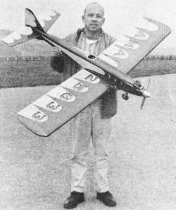
"Control room" of Whistler is exposed as Doc points to one of the Dzus fasteners which
hold wing. In his report, Seattle's famous radio-controlled dentist explains why he favors
this type of hold-down arrangement over the more conventional dowel and rubber band.
All photos here are the work of George Hickson of the Seattle R/C "ARKS" club.
Stabilizer frame is pinned in place over plan. When cement between joints is dry,
remove pins and cement 1/16" sheeting over framework as shown. Flip stabilizer over and
sheet in remaining side. Fin construction similar to stabilizer. Top block is carefully
cut out to receive fin and stabilizer and once satisfied with fit, fin and stab are cemented
permanently in place.
Model finishing is pretty much "old hat" to most of us, but a great number of modelers
have asked me how I get such a glossy light weight finish on my models. Here's how:
Sand model thoroughly, working down to a pretty fine grit of sandpaper, such as Wet-or-dry
#220. I use balsa filler-coat mostly to fill in the end grain of the fuselage blocks.
Now I'll tell you a little secret - it's not how much you put on, but how much finish
you take off. Sand lightly all over, eliminating all scratches. Two coats of dope should
give a glossy finish to the wood - add a third if necessary. About #320 grit Wet-or-dry
paper is used next. Silk covering is now applied, but do not use it over concave areas,
such as the wing fillets.
Brush on 6 or 7 coats of clear dope until entire model is glossy (every single square
inch). Sanding with #400 grit paper should kill the silk grain. Hold back on large open
areas; this is where we tend to cut loose too much and sand through the silk. Spray on
just enough color to get an even tone of color throughout. I generally use two coats
of the pigmented stuff. No sanding or rubbing compound at this phase. If you can stand
it, allow the dope one full week of curing time. Rub with auto body compound, then finish
up with Wright's Silver Cream.
Note that the Dzus fastener mount also doubles as the bottom trim bar rail. Assemble
the mount and upper trim bar rail to a 1/16" plywood plate and cement in place inside
the fuselage with about 1/8" between the retainer wire and the bottom of the fuselage.
Drill holes in the wing L.E. for 3/8" keying dowels. Make up temporary stub dowels with
pointed ends and force the wing in place in the fuselage to mark dowel locations. Drill
the forward ply mount and cement the final dowels in place in wing.
Take an approximate measurement from the wing T.E. for the Dzus fastener and probe
with a pin until you locate the exact position of the retainer wire. Drill 3/32" or 1/8"
for a visual check, then carefully ream out to 1/4" for Dzus fastener. A 3/32" plywood
ring on the bottom of the wing will prevent the stud from pulling through, as there is
a strong gripping action when the stud is given its quarter-turn locking action. Once
it is "in", there need be no worries as to it working loose, as it is vibration proof
and requires strong counterclockwise torque to loosen it from the locked position. (Editor's
note: Since the Dzus AJ4-55 fastener is not easily procured in most localities, we have
made arrangements for them to be made available by mail. A pair of AJ4-55's, with matching
wire springs, will be sent to any U.S. location for 50 cents (price includes handling
and postage charges). Send postcard for further information.)
As regards trim and flying, the first Whistler that I built required down trim for
most flying; this led to the use of 1 degree negative decalage. Just follow the angles
shown and your Whistler will perform to your complete satisfaction.
Use Bonner horns on the rudder, elevator and ailerons. On the elevator and aileron
horns, use the outer holes; for the rudder, use inner hole. This rudder is the proverbial
"barn door" which is swung through a large angle to insure positive spins. On the first
take-off, trim the elevator neutral and pull her up gently. You are now airborne with
a model that has the capability of performing the entire AMA pattern with an ease and
precision far above most other multi models.
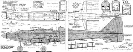
Whistler Plans Sheet 1
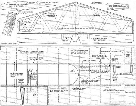
Whistler Plans Sheet 2
Notice:
The AMA Plans Service offers a
full-size version of many of the plans show here at a very reasonable cost. They
will scale the plans any size for you. It is always best to buy printed plans because
my scanner versions often have distortions that can cause parts to fit poorly. Purchasing
plans also help to support the operation of the
Academy of Model Aeronautics - the #1
advocate for model aviation throughout the world. If the AMA no longer has this
plan on file, I will be glad to send you my higher resolution version.
Try my Scale Calculator for
Model Airplane Plans.
Posted August 25, 2018
|