|
This was quite an undertaking
by authors Ed Sweeney and Fred M. Marks. They reported on practically every radio control
system that came new onto the market in 1969 and printed the findings in the 1969 Annual
edition of American Aircraft Modeler. That was still the era of galloping ghost systems
with reeds, rubber band-powered escapements, and some of those newfangled things called
transistors. By 1969, some of the transistors had graduated from germanium to silicon.
The authors actually get into a little detail on the dual conversion receivers with their
IF frequencies and selectivity - music to the ears of a radio guy.
From the R/C perspective, as the song goes, "These are the good old day," not the
days of the old equipment shown here.
1969 Radio-Control Equipment Survey
(see
page 2 for the equipment
specifications)
Comprehensive directory of all 1969 systems from single channel to full-house digital,
with data on controls, circuits and cost.
Text by Ed Sweeney; commentary on digital by Fred M. Marks
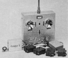 Galaxy 5 channel
THIS radio survey is the first of its kind in several years. The market recently has
changed vastly. Today's modeler has a choice of three types of control systems - inexpensive
dry-battery-operated sequential sets, medium-priced proportional systems of up to three
independent controls, or going first class with full-house multi-digital proportional.
Each of these categories offers fine quality equipment suitable for different applications.
Some systems are expandable to more controls, some are kits, and some are just for sport
or fun flying.
Our survey is designed with two pur-poses: 1) to be a buyer's guide of what's available
in each category, showing what it operates, how it works, and what it costs; 2) to give
enough technical information for a meaningful comparison between the features of each
system, including data that provides possible interchangeability between one system and
another.
For effective presentation we have limited this year's survey to systems manufactured
in the U. S. or Canada, but including equip-ment manufactured abroad for sale here -
provided service-after-sale is available, too. We are interested only in systems for
sale in 1969 and those units continuing from 1968 in full production for 1969. Discontinued,
or no-longer-in-production systems, are not shown, although they may be available brand-new
at some hobby shops.
No evaluation of control systems is made. All the equipment mentioned is top rate,
excellent in design and performance, and of reasonable price. It would be impossible
to fully review and evaluate each set. No systems are knowingly excluded.
The groups: The role of a sequential system is two-fold.
First, it started R/C. All we had when Walt Good, Chet Lanzo and Jim Walker first
tried R/C were escapements, tubes, ground-based car-battery-powered transmitters, and
rabbit-ear antennas. Now we have very light, simple, compact, dry-battery (the cheapest
kind), and highly refined sequential systems.
Second, we have more elaborate sets with motorized sequential actuators operating
with pulse-counter-equipped transmitters, which are hand-held units, and superhet receivers.
Three most appealing features of sequential systems are low-cost purchase and operation,
non-wagging single-channel action, and easy use. For glider flying, low-current consumption
is important. Sequential systems with only occasional command operation allow the least
battery supply, yet powerful servo movement when called for. All a small glider needs
is steerage and occasional elevator trim; a sequential set does the job fine. Small-field,
and trainer types also go great with sequential rigs.
A proportional single-channel system, or anything up to three channels, is our medium-priced
spread. Proportional usually means bigger and more expensive batteries, mechanically
better servos, continuous communication between transmitter and receiver, a pulser in
the transmitter, and more elaborate output from the receiver. Weight is generally more
than with sequential systems. But, proportional is better because it is easier to fly
and more like the real thing. The cost is usually worth the performance improvement.
Pulse proportional systems can be very simple and use light batteries, such as sets
with magnetic actuators. Smooth-working linkages are essential, and only small planes
of less than 19 power are recommended. For learning to fly, especially if one will some
day get an elaborate multi-function system, rudder-only pulse with add-on motor control
is great.
Most rudder-only systems can be expanded to servo action with Galloping Ghost servos
or with dual-servo high-pulse-rate systems. This is elementary and dependable multi flying.
Again, control installation is more critical but the performance is still better. Current
drain is higher, so bigger batteries will be needed. Better pulsers are essential for
good operation, and bigger-than-19 planes can be flown.
Some pulse-servo proportional rigs can be expanded with kits for servo amplifiers,
decoders, and the like. So doing, is fun in itself and gives one a real multi system,
although with only two proportional and one trimmable function. Such sets offer variable
pulse width, variable pulse rate, and solid signal-on and solid signal-off. This gives
rudder, elevator, and motor controls.
Feedback servos for two proportional and one trimmable operation can be built and
will be available in kit form. Therefore, you can expand up to this performance.
The best of the medium-priced range are the three-channel proportional systems with
all-feedback independent functions. Transmitter has usually one two-axis control stick
and a proportional, or positionable, lever to operate a proportional feedback servo for
such operation as throttle. Servos are the same as in the full-house systems, and most
of the transmitters and receivers are identical with the bigger rigs. In fact, many of
the three-channel systems can be expanded by their manufacturer to more than three channels
for additional expense, or at least the servos, battery packs and charging equipment,
can be used with a new transmitter and receiver, offering more functions. One or more
additional servos would be needed.
With three functions, there is no limit to what can be operated - big-engined planes,
large soaring gliders, boats, cars, etc.
It is common practice to use three-channel sets in planes normally flying with four-channel
rigs. This is done by electronic or mechanical coupling of rudder function with ailerons.
If mechanical, a linkage does the job; if electrical, a second parallel-wired servo is
used. Flying with coupled aileron and rudder is not too different from having independent
functions and is better sometimes, as with high-wing planes.
The user can further modify the three-channel set to have so-called 3-plus-1 action.
Here, a set of microswitches on the throttle servo cuts in or out the electronically
coupled rudder servo. Primary servo is aileron. One way to set this up is with coupled
functions at full high throttle and full low throttle, but to have ailerons only at all
intermediate engine speeds. Switches just close contact in the signal lead to the digital
servo.
To add meaning to the three functional economic groups, we will give as brief as possible
description of single-sequential-function gear up through multi full-house digital.
In single-channel the use of one tone transmitted by a constantly on carrier or radio
frequency is the information to the receiver for operating a control.
In sequential single-channel, the tone causes a switching action of an escapement
or servo. An escapement is a rubberband-powered device on which rotating arm is released
and caught by movement of an armature controlled by a magnet from the receiver. A linkage
operates the control surface from the rotation of the arm. In the escapement is a shaft,
hooked to the wound-up rubber band. The shaft and arm are allowed to rotate a quarter
or so turn from neutral, giving a mechanical output. So, indirectly, the tone moves the
shaft, and the device has several points in the rotation at which it can be stopped.
These points give neutral, right-rudder, left-rudder, and a third position (which is
actually neutral rudder but allows wiper contacts to trigger another device), and these
are in sequence.
A motorized sequential actuator does the same thing as the escapement, only wiper
contacts replace the armature and rotating shaft. Movement of servo is powered by a motor.
The same functions are available in the same sequence.
The tone of the single-channel set can be turned on repeatedly with a pulser. Tone-on
gives rotation of servo motor one way, and tone-off gives opposite rotation. With linkages
and gearing, the rotation gives right- and left-rudder movement. Therefore, if the tone
is turned on as much as it is off in a given period of time, the rudder goes equally
right and left. To the airplane this is neutral effect.
At the control stick on the transmitter we can vary the percentage of on-off time,
and at the plane have variable rudder positions. Rudder position is proportional to control-stick
position. Thus, we have pulse and proportional operation. The above describes rudder-only
pulse proportional.
A Galloping Ghost system adds another operation available with the one tone, that
of changing the rate of the pulsing. This can be done without affecting the percentage
of on-off time and therefore is a second independent pulse proportional function. Galloping
Ghost servos respond to the pulse-rate changes for the elevator functions. Usually, the
rate range is four to 12 pulses per second, with six pulses per second for neutral. The
function is mechanically detected by the servo.
Since the GG servo oscillates back and forth, not making a full revolution, we can
obtain a positionable function by having an arm on a gear downstream of the output gear
for rudder, that is moved several degrees when the rudder gear makes a full rotation.
By the direction of full rotation of the rudder gear, the arm of the down-stream gear
is moved forward or backward. This is normally hooked up for the motor-speed control.
Full rotations either way are achieved by solid-on or solid-off tone; the control is
trimmable, and during throttle changes, the rudder wags at neutral and the elevator in
up elevator. This throttle arrangement is mechanically detected pulse omission, or more
simply, solid-on or -off tone.
Briefly, a two-servo single-channel system operates just like Galloping Ghost, except
at much higher pulse rates and with electronically detected pulse-rate changes. In all
systems fast pulsing is down elevator and slower pulsing is up elevator. More elaborate
decoder single-channel systems with three servos are possible, but none are described
in the survey. The third servo, for motor control, would operate on electronic pulse-omission
detection.
A digital system, whether it is a one, two, three, or as many as eight functions,
is a basic pulse-width device. Here, the transmitted radio frequency is pulsed on and
off - not a tone. The pulses are electronically measured with reference to time and position
within a set of pulses or a frame. Each servo gets one of these pulses. In the servo
an electronic amplifier adjusts the servo position to correspond to the percentage of
on-off time of each pulse.
The servo does not pulse at all- this is called feedback-servo operation. More detailed
description follows in the discussion of multi-digital proportional. What is given here
is reference with single-channel pulse systems only.
DIGITAL SYSTEMS
The survey of digital systems will attempt to be more than a simple listing of equipment
available from various manufacturers in that specific performance is given where available.
In setting up such a survey, the primary question is "What is important to the survey
reader and why is it important?" We will establish this rationale here in the hope that
it will make the survey most meaningful.
It appears that flyers generally fall into distinct classes: those who couldn't care
less what makes the thing tick so long as it ticks, those who wish to learn the rudiments
of the equipment in the hopes that it will aid them in selection of a system the most
useful to them, and those who like to build, or at least maintain and repair their equipment.
I feel that there will be data here useful to all.
For the prospective buyer: Those preparing to purchase their first
set will generally be guided by price, intuition, and what the local pros (if any) prefer.
The following observations apply in terms of the utility and mechanical arrangement of
the systems.
There are three frequency bands available: 27mhz, 50mhz, and 72mhz. Not all equipment
is available on all frequencies, and the modeler is not permitted to operate in the 50mhz
band without a technician's license. There is basically no difference in performance
available on all frequencies and selection is dependent on local interference and the
number of flyers in given frequency slots. Prices on 72mhz are somewhat higher for some
systems and 72mhz crystals are more expensive.
The number of channels required will generally be determined by the modeler's specific
control requirements. In general, it is felt that maximum utility is provided by purchasing
a four- to six-channel system which will cover your ultimate needs with whatever number
of servos your budget will sustain.
Stick arrangements are: two sticks with trims and auxiliary levers for channels beyond
four, or; a three-axis stick with aileron and elevator controlled by the stick, rudder
by knob on top of the stick, and throttle control by a lever; or a two-axis stick for
elevator and aileron, plus a separate self-centering lever for rudder and a lever for
throttle. The two-stick arrangement normally has elevator and aileron on the right-hand
stick and rudder and throttle on the left-hand stick, commonly called Mode 1. There are
a number of control arrangements such as throttle right, elevator left to separate aileron
and elevator, etc., which can be set up optionally.
Airborne equipment mounting is usually a variable feature with clip mounting, mounting
brackets, as well as the more common mounting lugs with grommets.
What performance characteristics mean: Proportional control systems
in the past were analog instead of digital. Within limits, different servos could be
used with most analog systems. With the advent of digital systems, the simple analog
signal was replaced by a more complex digital control pulse which varies from system
to system and makes interchangeability more difficult.
Briefly, the digital system transmits a repetitious series of pulses about five micro-seconds
wide, spaced a nominal 1.5 milliseconds apart. This series of pulses will total one more
than the number of channels available. The series of pulses totals 1.5 times the number
of channels, in milliseconds. This series of pulses is followed by a pause of several
milliseconds for system synchronization. This sequence is then repetitive. The total
length of the set of information pulses and the synchronization time is called the frame
length and varies for each system. The inverse of the frame length is the frame rate,
or repetition rate. Channel command variations appear as changes in the nominal length
between each succeeding information pulse.
The decoder accepts the series of transmitted pulses and decodes them sequentially
to produce a pulse for each servo. The length of this pulse is determined by the relative
position of the transmitted pulse. The characteristic of this decoded pulse determines
the design of the servo. The variables associated with the decoded control pulse are:
its polarity which can be either positive or negative going; the nominal width which
you will see in the survey ranges around 1.5 milliseconds; the amount of pulse-width
variation about the nominal pulse width, usually around plus and minus 0.5 milliseconds.
Thus, it can be seen that within limits, servos can be used compatibly with systems other
than that for which they were designed.
The receiver characteristics and techniques are presented, not as a measure of capability,
but as a matter of interest to illustrate how many ways the design can be done and still
be successful. All perform well and no one design approach offers an outstanding advantage
over another. The sensitivity of the typical receiver runs around one to five microvolts
for full control. Those at the lower end must be quite selective to reject unwanted signals
while those with higher signal level requirements generally have slightly higher transmitter
power requirements.
Receiver selectivity is becoming an increasingly important consideration in a high-interference
environment. Typically, the required selectivity is obtained by means of a double-tuned
front-end and the usual IF strip. In some cases, RF amplification has been introduced
with the advent of the Field Effect Transistor. The high level of sensitivity achieved
in digital receivers makes the use of automatic gain controls (AGC) an absolute necessity
to prevent receiver swamping and output variation with range. However, note the multitude
of ways in which it is achieved, all satisfactory!
Decoders offer an equally wide variation in technique with the use of SCS's predominant
and the use of integrated circuits increasing rapidly.
What can be forecast: Some of the trends are relatively apparent
such as the reduction of airborne system weight and Volume. Others, such as the use of
new circuit concepts are not as predictable. The weight of the average four-channel digital
airborne system has been reduced from around 24 ounces for the preceding generation to
12 to 14 ounces for the current generation. The 12- to 14-ounce weight is achievable
with discrete components and present serve mechanics and motors.
The next generation of airborne systems in the four-channel class appears to be headed
for the eight- to 10-ounce weight bracket. However, this requires the application of
integrated circuit design in at least the servo amplifiers. Just over the horizon are
airborne receivers having not much over a one-inch-cube Volume and servos weighing about
one ounce.
With respect to circuitry, the use of RF amplification in the front-end will probably
become universal as has double-tuning followed perhaps by triple-tuning. The use of pre-tuned
ceramic-filter IF strips may also see extensive use, probably in conjunction with integrated
circuitry.
One observation bears note by our domestic manufacturers: the introduction of frequency
selection by field-change crystals in the German-made equipment. The normal reaction
is to say it can't be done economically but remember, about three years ago it would
have been emphatically stated that a 10-oz. system couldn't be produced economically.
The second observation is based not so much on the survey as on personal observation:
the impact of kitted digital systems is having a tremendous effect on the hobby, primarily
because of the price aspect. Newcomers are coming into R/C at a sharply rising rate as
a result. They then proceed to more sophisticated equipment with the advantage of a fair
working knowledge of the digital system.
Continued on Page 2
Posted May 14, 2011
|