|
Flying wings have always been a popular design subject.
The closest most of us have ever come to owning a flying wing is a combat type control line or radio
control model. Flying wings are identified by a lack of separate, defined fuselage. Stability issues
make flying wings a challenge, and is why they are not seen as often at the field. That goes equally
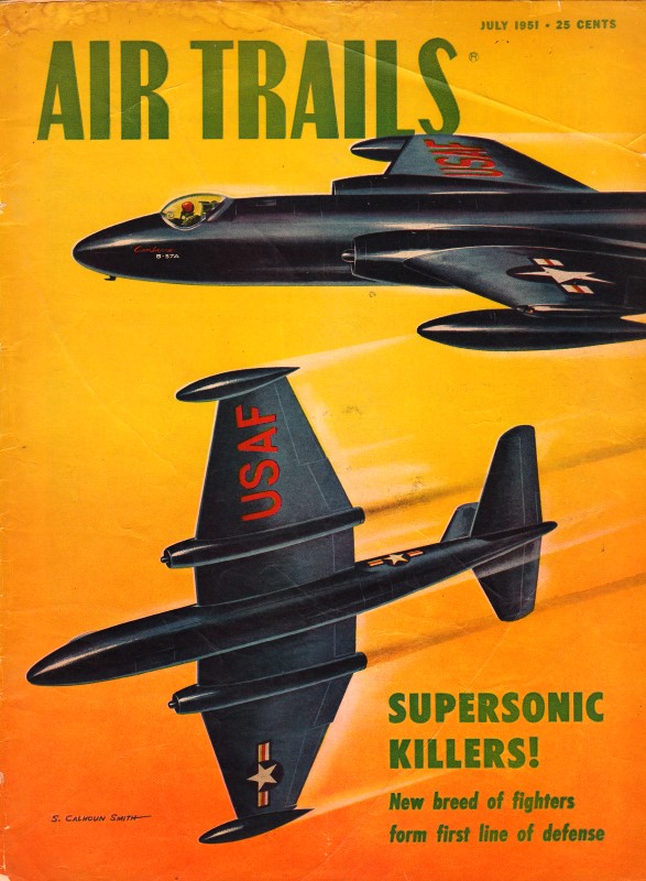
for both model airplanes and full-size airplanes. In 1951, Air Trails magazine published this
article on the topic of flying wings in order to help spawn an interest amongst modelers. It contains
a lot of useful information that is still applicable for anyone who would like to try his hand at a
flying wing. If it is possible to build a flying, controllable model of Snoopy sitting atop his dog
house or a witch atop a broom, than surely a flying wing is not out beyond the realm of possibilities.
Flying Wings Turorial

AT's monthly design contest has a fascinating subject. Are you sending in entries? See rules pg.
38 on how to enter
The basic problem of the Flying Wing is longitudinal stability. When the angle of attack is increased
on a standard airfoil like the Clark Y, the center of lift moves forward, tending to increase the angle
of attack until the wing stalls. On standard designs, the stabilizer prevents the wing from doing that.
By using a special airfoil, which has a reflex or turned-up trailing edge, the center of lift remains
at the same point, or it may actually move backward and so introduce a stabilizing moment.
The stabilizing action of the reflex trailing edge airfoil can be visualized by assuming that the
airfoil consists of two sections: a front portion which does the lifting, and a rear portion which takes
care of the stabilizing. A check on the center of lift position of the reflex air foil will show it
to be about 22% of the chord in contrast to 35% on regular airfoils. This could mean that most of the
lift comes from the front portion. We might go further and cut a reflex section into two pieces so that
front will be two-thirds of the total, and the rear one-third. If we leave a slight gap between the
two sections, the arrangement will be similar to a very close-coupled standard wing-stabilizer layout.
The reflex trailing edge will be equivalent to a negative stabilizer.
Knowing that a Flying Wing is nothing else than a close-coupled arrangement of wing and stabilizer,
we do not have to use reflex airfoils to obtain longitudinal stability. We can use airfoils like Clark
Y for major lifting requirements, and add the necessary stability area where it will do most good. But
we won't have a true Flying Wing.
By using an extremely pronounced reflex on the trailing edge, it is possible, without using sweep
back, to make a Flying Wing that will look like a plank. However, such designs are limited to gliding
or to flying speeds just above the glide. Increase of speed beyond this point would introduce looping.
The lift capabilities of reflex airfoils are much lower than those of the Clark Y type. This means
that, area for area, Clark Y will lift more. Therefore, there is no loss of efficiency if we do use
a Clark Y in combination with a non-lifting stabilizing area.

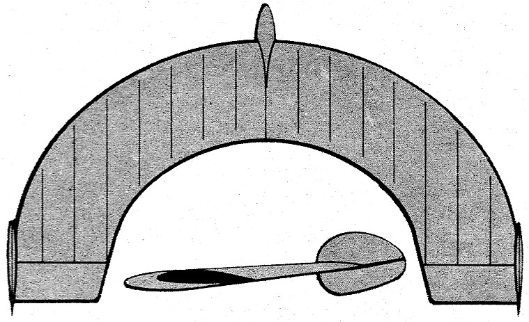
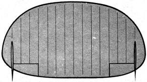
This Half-Moon shape has been tried with differing success. Quite hard to construct. A considerable
portion of main lifting area is forward of midpoint. This results in tips having a relatively long moment
arm which gives a desirable stabilizing action.
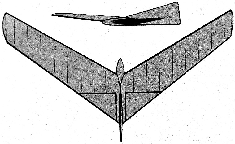
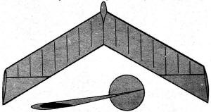
By employing Clark Y in combination with a sweepback, it is possible to obtain a stable model by
having tips set at a negative angle in relation to the center section. When such a design is analyzed,
we find it to be a close-coupled standard arrangement, with tips acting like the stabilizer. The sweepback
provides the illusion. The stabilizer, instead of being in the center, is divided into two sections
and placed on the tips.
As a rule, it is relatively easy to make Flying Wings fly as gliders. But it is another story when
power is applied. Like any other short-coupled design, it has an inherent urge to loop whenever speed
is increased beyond the glide range. This definitely limits the Wing to sport flying as it cannot be
made to compete with standard high-speed models. If excessive power is applied, it will be converted
into looping without exception. If you are determined to counteract looping with downthrust, be prepared
to use as much as 20 degrees downthrust while having the engine way up above the C.G. A well balanced
Wing is capable of very tight circling, and will ride the thermals with the best of them.

Swept-forward design which was tried during last war in full-scale form for towing; proved not too
reliable. Model version should have sufficient negative setting at center section to provide normal
stability. Use little dihedral to minimize spinning.
When a reflex trailing edge airfoil is used, the sweepback may be very small. But as the airfoil
changes towards Clark Y, the sweepback angle should be increased. The only logical reason for the increase
is to obtain a longer moment arm for the stabilizing tips. We can make a rough rule for sweepback angle.
If a reflex airfoil has none, and Clark Y has 30 degrees, airfoils in between will have sweepback angle
determined by their looks or relationship to reflex or Clark Y. This also means that if you want to
use deep under-cambered type, the sweepback will have to be more than 30 degrees to provide the needed
moment arm for the tips.
Although a streamlined airfoil with a center of lift travel similar to reflex type airfoils might
b utilized here, you'd be safest with a reflexed section. Big problem with such a design is its extreme
susceptibility to speed variations - not so very good.
Dihedral angle can be very small on Flying Wings. One inch under each tip for every foot of span
is more than enough. As for type of dihedral to use, a straight "V" seems best.
Somehow we never seem able to understand the exact function of the drooping tips. Nor the purpose
of generous dihedral at center, only to have it level off at halfway mark and then droop or come up
again .... If you -think that you have dihedral troubles, increase or decrease the dihedral as a whole
so that you will know just what does happen.
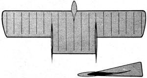
Excellent experimental design. Wing setting of center portion is uniform to rudders. The adjustable
tips, outside downwash airflow, are set almost at zero angle of attack. Difference between tips and
main section gives the effective angle of attack.
Rudders should be on the generous side because they have a very short moment arm. Although you may
have them out at the tip, their action about the C.G. has a small moment arm. You can tell if you have
too much or too little rudder area during the tow. Not enough rudder area will give you towing troubles.
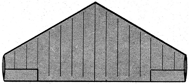
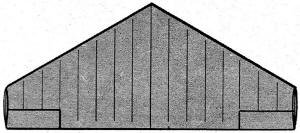
This is a close approach to a true flying wing. The tip sections have a stable M-6 airfoil, while
center section has a pronounced reflex trailing edge. This type will fly well as long as speed remains
uniform, thus resembling the triangular shape (opposite).
If you place the C.G. at 25 % of the average chord when using Clark Y, and at 20% when using reflex
airfoil, perfect stability should result no matter what type of Flying Wing you are using. It is, of
course, understood that you will fulfill the rest of the requirements; such as providing the required
negative angle on the tips to produce a smooth glide.
By having the C.G. at the 25% point, the arrangement will have the super-stability layout. Both surfaces,
the wing and the stabilizer tips, will be lifting behind the C.G. And just a slight change in the airflow
will make the tips bring the Wing into the new airflow. This type of positive control can actually be
observed. When such a model is disturbed it will be seen to "shimmy" back into smooth flight. In contrast,
a model having the C.G. further back will develop oscillations which will end up in a dive.
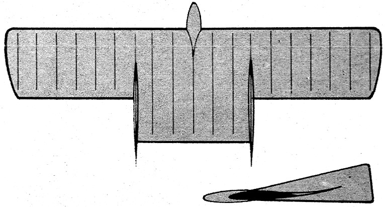
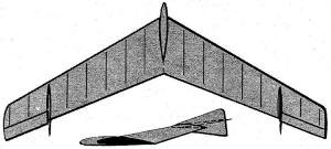
An old standby, and a popular design recommended to newcomers. Here an M-6 airfoil is featured with
adjustable wing tips for establishing control. This type works out well for power flying. More of these
built than all others combined.
It is a fact that if the C.G. is placed at the 25% point, all other items will then be automatically
brought to the correct position. If you are using large tips, the negative angular change may be slight.
If tips are small, the angular change will be great. You should be generous with negative tip area,
otherwise you might have to use 30 degrees "up" movements which are bad drag producers.
When a wing has a gradual washout to negative tips, it is very difficult to find the average chord
on which to base the 25% C.G. position. In such a case, it will be necessary to find the C.G. position
by test.
The Flying Saucer approach. Reflex airfoils are essential here. Design extremely sensitive to power
when used in free flight. Chance-Vought had full-size ship with two articulated props which took ship
off at high angle of attack much like helicopter.
Add enough balance weight to obtain a smooth glide. Now watch how the model takes upsets. If it starts
to nose up into stalls and then dives, and repeats this action until it dives into the ground, the C.G.
is too far back. Add more balance weight. Of course, this will produce diving tendencies. Correct by
giving the tips more negative angle.
We seem to contradict ourselves. Here we have a model that has stalling tendencies which we correct
by adding weight, only, seemingly, to bring back stalling by giving tips greater negative. All we can
say, try the system and you will be surprised. Carry on this procedure until the model just "shimmies"
into a smooth flight" when it is upset.
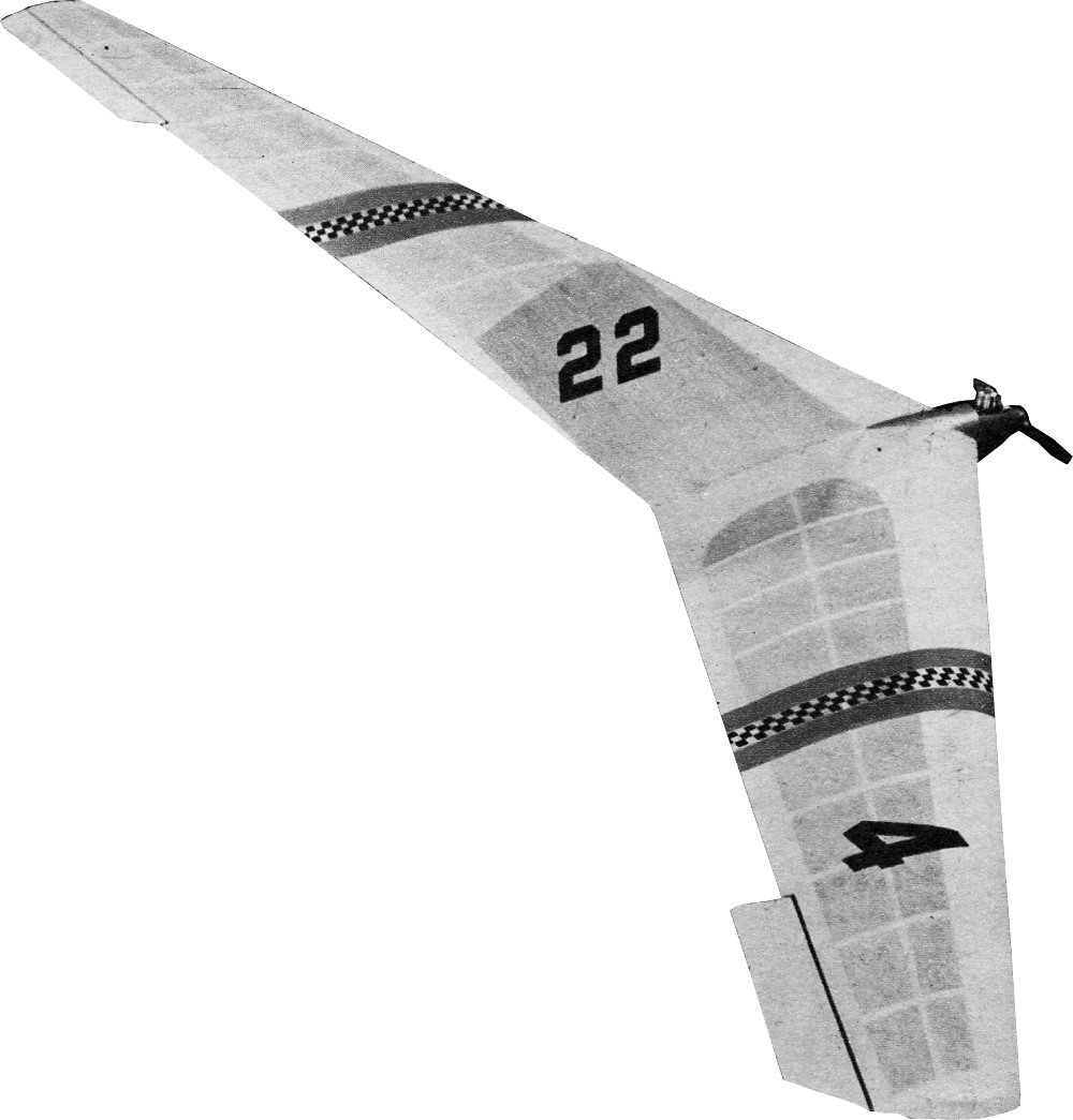
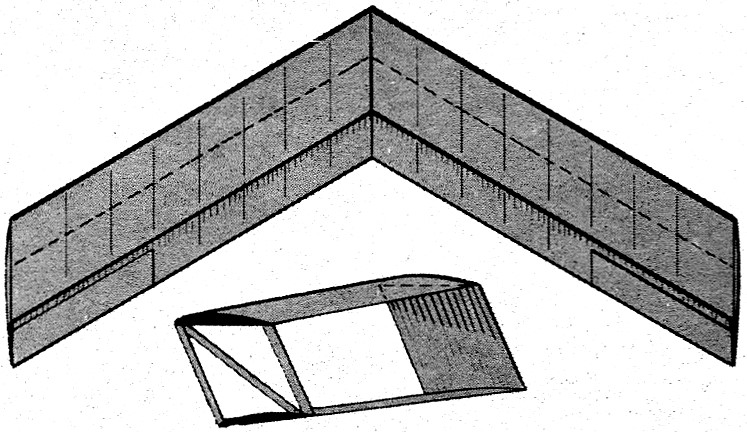
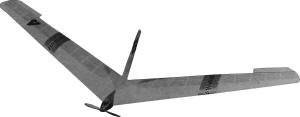
The top design model selected is a combination of compromises. Notice its large size in relation
to the power used. This will discourage looping yet provide fairly good climb. Since reflex airfoil
complicates construction, Clark Y type airfoil is used in combination with 30 degree sweepback and 10
degree washout at the tips. To provide control and adjustments, the tips are adjustable. Rudder is generous
to provide smooth towing. Also, this model can be used as a glider and as a powered model.
A feature was the claim that this particular type of construction - balsa covering leading edge and
caps on top only - would automatically produce washout after the paper had been water doped. Since it
is a complicated procedure to plot out ribs with gradual washout change, we gave the idea a try. It
worked out as per claim. Not only once, but twice, since the first model was lost out of sight while
making glide tests.
After the ribs are cut, the wing is assembled as usual. Join the two halves so that correct dihedral
is obtained. You may have a bit of trouble covering with balsa sheet. But if you use a uniform and almost
quarter-grained balsa sheet, you will find that it will follow the rib outline without trouble.

Shades of the past! This biplane combination was used many years ago. Lower wing is set at negative
angle. The tip rudders are used to separate the two wings as well as provide the required rudder area.
Tricky design for use in modeling field.
Before covering with sheet, shape the leading edge so that it will "flow" with the rib outline. Otherwise
it will be difficult to obtain smooth covering.
Cement the sheet to the leading edge first. Let the cement set well before bending it down to the
ribs. Use weights to hold it in place. After the sheeting is done, cement cap strips in place. Note
that lower or bottom portion has no sheeting or capping. But do not forget the wide capping at the bottom
center to which the keel is fixed.
Cover the wing with wet Sky Sail. Although the construction will automatically produce washout, it
is wise to prepare a drying jig so that the tips will have about 10 degrees negative.
After paper has dried, apply several coats of clear dope to prevent it from tearing while you work
on the center section.
Cut keels. "A" and "B" to outline shown, and make the firewall to size. Cut leading edge to provide
a square face for the firewall. The keels will automatically position the firewall at the required angle.
Note that it is negative in relation to the center airfoil. Cement "C" corner blocks. .
After keels and firewall are set, form the streamlined fairing. Start by cementing the sheet to the
keel, and then cut to approximate outline to fit the airfoil. Paint finished fairing with several coats
of cement and dope mixture to obtain hard surface.
Note the addition of extra 1/4" balsa block to obtain good foundation for spinner fixing. The spinner
is cut to fit the engine you will use, and it is held to the firewall by three wood screws. When flying
the model as a glider, use the front portion of the spinner. You might have to use a wedge to hold it
in place, or you may find a screw to fit and so hold it in place. Finish the model by adding the
adjustable tip tabs. Use copper wire for hinges. Trim to suit but do not use much colored dope. Keep
weight low.
Since the model has a gradual washout, it is impossible to find the exact average chord on which
we can pin the 25% C.G. spot. However, the original model balanced as shown on the plans. Therefore,
place enough clay in the spinner to bring the C.G. to the spot indicated. Now try some glide tests.
If the model dives, use the tabs to bring it to smooth glide. If it stalls, add more weight - remembering
what was said about how to find the best C.G. position by observing the flight pattern.
Do not attempt to force a definite turn on the model. Let it follow its built-in setting. Of course;
if it is too violent, use the tip tabs. As you may know, always use "up" adjustment. If you want the
model to turn to left, "up" the left tab. Moving the tab "down" does not work out as per aileron effect
as one would expect.
The original model was quite easy to tow. But we must confess that the turn setting was not very
powerful. Tighter turn setting may require auxiliary rudder control. In connection with tight turns
you will find that you may have to "up" the tabs to prevent steep spiral descents. This is normal. Leave
balance weight alone once you have obtained a smooth and stable straight glide. Make all flight corrections
with the tabs.
Do not expect spectacular climbing ability from a Flying Wing. It is not made for that sort of work.
If you had automatic control, the situation would be different. But if you expect the model to have
a good glide after the power is out, be satisfied with moderate and controlled power flying.
 If
the model has stalling or looping tendencies, reduce power by changing props, or adjust for a climbing
turn if stalling occurs in a straight flight. If you follow this procedure, you can count on having
a lot of fun with, your Flying Wing. If
the model has stalling or looping tendencies, reduce power by changing props, or adjust for a climbing
turn if stalling occurs in a straight flight. If you follow this procedure, you can count on having
a lot of fun with, your Flying Wing.
When designing your own, remember the basic position of the C.G. at 25% point. If you do so, all
other factors will be automatically adjusted for this condition and a stable Flying Wing can be guaranteed.
About the Designs: You are not required to build a model in this contest! All you do is submit detailed
3·view drawings of your favorite "brain-child" in each of those categories listed (plus sketches if
you are artistically inclined). These drawings should not be less than 8 x 10 inches and must show dimensions.
Give data on wing sections and settings, cross sections, center of gravity, weights, proposed power
and the like. It's not your drafting skill that will win, but your designing ability and imagination.
AT selects meritorious designs and presents them in 3-view form; payment of $5 will be mode for each
one published. The top design each month will be built and test-flown by AT's design and research team
and the model will be given to the winner with all the equipment that goes with it. Categories: You
have until July 1, 1951, to get your design studies in the mail for combination R.O.G.-R.O.W. sport
free flight featuring interchangeable landing gear for any size engine - model should not be of amphibious
(flying boat) type; until Aug. 1, 1951, to have entries postmarked for Half-A free flight using any
size engine up to and including .050 cu. in. disp. Send Your Designs To: Air-Model Design, c/o Air Trails,
304 E. 45th St., New York 17, N. Y. Decision of Air Trails staff is final; no entries will be returned.
Posted January 17, 2015
|