|
If you have been looking for an unusual project
that should build fairly quickly, cost very little, contain non-standard materials, and
qualify for a vintage design contest, then Rathgeber' "Minimum" fits the bill. It is
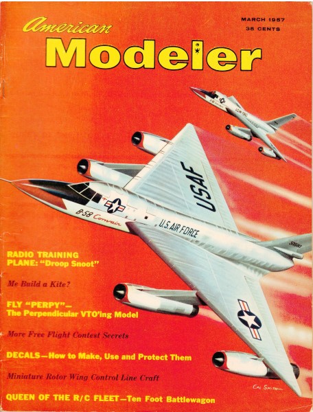
a 1/2A control line speed model with about an 8" wingspan that appeared in a 1957 issue
of American Modeler magazine. It does not appear to have been intended for serious
competition, but given the single-line control and extremely high thrust-to-weight ration
and minimal drag design, it might have been a contender back in the day. Designer George
Rathgeber does not give specifics on timed flights. My guess is that it was a handful
to fly due to lack of tail feathers.
Rathgeber's "Minimum" C/L Speed
 By definition minimum is the least quantity or
amount possible. Here's our attempt to arrive at the minimum quantity in a Half-A speed
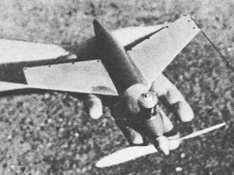
model The simple design results in extreme low weight of 2 7/8 ounces and short construction
time. A single line and elimination of the empennage reduce parasitic drag. By definition minimum is the least quantity or
amount possible. Here's our attempt to arrive at the minimum quantity in a Half-A speed
model The simple design results in extreme low weight of 2 7/8 ounces and short construction
time. A single line and elimination of the empennage reduce parasitic drag.
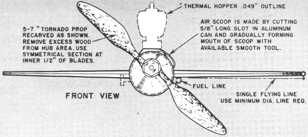
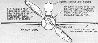
The plane wall designed around the Cox Thermal Hopper engine. An aluminum Ansco 120
color film pack was used as the fuselage. These cans are available at color film processing
shops.
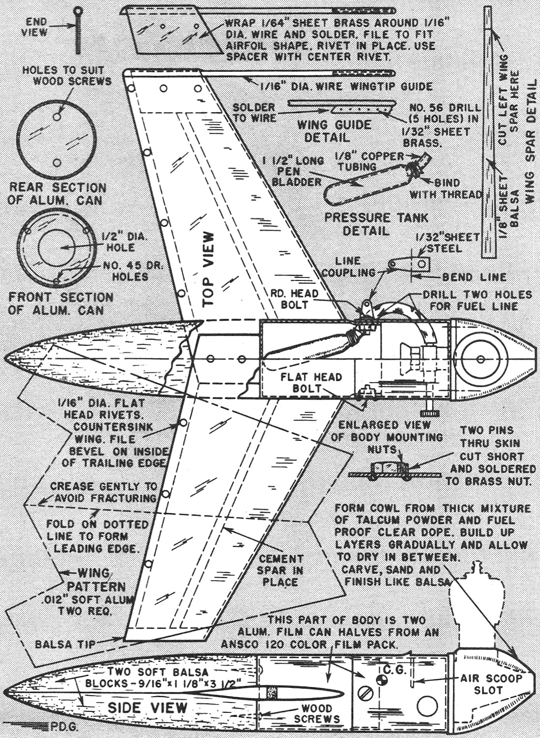
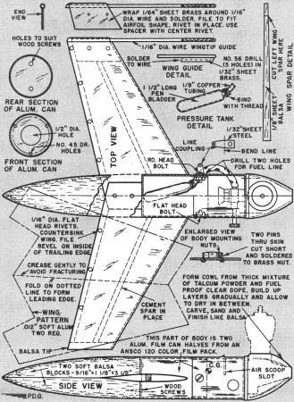
The wings have a symmetrical airfoil; it is not necessary to differentiate between
the left and right until joining them. The spars do not go through the fuselage. Join
the two wings with rivets and glue them to the male half of the aluminum can as shown
in the plans. Be certain the wings are on center line of the can and have zero incidence.
(When the most efficient wing tip guide hole is determined by flight tests remove
the metal containing the remaining holes with a file or grinder.)
 The mounting flange on the Cox Thermal Hopper
engine is slightly larger than the front end or female half of the aluminum can. This
was disregarded in the original construction but it can be compensated for by filing
the engine flange down to the proper diameter if you insist. The mounting flange on the Cox Thermal Hopper
engine is slightly larger than the front end or female half of the aluminum can. This
was disregarded in the original construction but it can be compensated for by filing
the engine flange down to the proper diameter if you insist.
Engine mounting bolts are 2-56 x 1/4" brass screws. Nuts must be filed away on one
side to fit inside the aluminum fuselage. Two 2-56 x 1/4" screws hold the fuselage sections
together. The screw on the right side has a flat head, so depress the aluminum around
the screw hole to simulate a countersink. Also depress underneath aluminum to allow slide
fit of the two fuselage halves.
Complete the construction of the engine cowling line by following the instructions
on the plan. First cover the engine intake and exhaust parts with tape to prevent dust
from entering the engine. Apply "paste" to the motor in heavy layers. Allow it to set;
carve it to size after a few hours. This engine faring will become very hard when completely
set.
To finish the cowl and balsa portion of the fuselage, brush on a few coats of a thin
talcum powder and dope mixture on balsa. Apply ten coats of a fuel proof colored dope,
sanding with #600 wet and dry paper between the fifth and final coats. Rub down with
automobile compound; polish with a good paste wax.
The gas tank is a pressure type. The fuel is injected with a syringe which has a six
inch piece of flexible tubing forced partly onto the nozzle. The inside diameter should
fit snugly with the outside diameter of the fuel line used. To "gas up," remove the fuel
line from the intake nozzle and squeeze fuel into the tank with the syringe. Clamp the
fuel line tight with a pair of pliers and replace line on nozzle with the pliers. Make
sure the needle valve is completely closed before starting this operation.
A hand operated geared starter is a great asset in starting the engine. Gradually
open the needle valve as prop turns and instant starting occurs.
In test flying, select a guide hole slightly to the rear of the C.G. This will give
a nose out condition and keep the flying line taut. In subsequent flight test, the forward
holes should be tried until the maximum speed is attained.
A hand launch is used with the "Minimum." Important elements for a successful hand
launch are a smooth follow through motion of the arm and hand. The nose of the plane
should be inclined about 20 degrees when launched. Keep the flying line tight and launch
at a tangent to the arc.
-George Rathgeber
Rathgeber's Minimum Plans
Notice:
The AMA Plans Service offers a
full-size version of many of the plans show here at a very reasonable cost. They
will scale the plans any size for you. It is always best to buy printed plans because
my scanner versions often have distortions that can cause parts to fit poorly. Purchasing
plans also help to support the operation of the
Academy of Model Aeronautics - the #1
advocate for model aviation throughout the world. If the AMA no longer has this
plan on file, I will be glad to send you my higher resolution version.
Try my Scale Calculator for
Model Airplane Plans.
Posted November 3, 2018
|