|
Newcomers are entering the realm of free flight aeromodeling all
the time, so it is never a waste of time or print space to post
articles giving instruction and recommendations on how to be successful
at the sport. Heeding the advice of accomplished, experienced modelers
is always recommended if you are having trouble correcting certain
issues with flight trim, structural integrity, component selection,
etc. Even if specific discussions do not apply directly to your
concern, often times it will spark an idea of your own. This article
provides a good rounded collection of information that should prove
valuable to most readers.
Secrets of Free Flight Endurance
By Thracy Petrides
Rubber powered fans will welcome this highly informative article.
Herein, Mr. Petrides clearly discusses the principles governing
flight characteristics of model planes and their proper application.
It goes without saying that if a task is to be performed it should
be done in the most efficient manner. Our task (Or is it? Ed.) is
to design and build a rubber powered model for maximum endurance.
In order that we may undertake this work efficiently, we must have
a thorough understanding of what our problem entails. Therefore,
with this in mind, let us enumerate the factors that an airplane
must embody for successful flight, and call these the "given." They
are:
1. A means of lift.
2. A means of propulsion.
3. Stability.
Next we must have an object, and, of course, this is endurance.
Now our problem is to efficiently utilize the factors "given" so
that we may obtain the most satisfactory "object" possible; or in
other words, to get maximum endurance.
Before we delve into the aerodynamics of the subject; let us
clearly understand what we mean by endurance. If a clock mechanism
consumes one tenth of the total energy of the spring daily, the
clock will last for ten days. Accordingly, the endurance of the
clock is ten days. Similarly, the endurance of a model is the sum
of the endurance of the power plus the endurance of the glide.
We can now clearly see that the endurance of a model is directly
concerned with the attainment of the maximum endurance in the power
and in the glide. Expressing these symbolically, we have, Total
Endurance = Endurance power + Endurance Glide.
Let us investigate each of these units separately. The amount
of energy that can be stored in a rubber motor is only dependent
upon the weight of the rubber. Just as much energy can be stored
in twenty strands of 1/16" flat rubber as can be stored in ten strands
of 1/8" rubber of the same length.
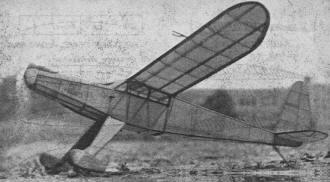
This Porterfield-Turner flying scale (August,
1940, F.A.) exemplifies careful application in design of the tail
surfaces, wing setting and propeller. It is a consistent performer
with long flat glides.
The amount of power that is available from brown rubber was found
by J. P. Glass, to be 30,000 inch ounces per ounce of rubber. This
means that, provided the energy could be utilized properly, it would
lift one ounce 30,000 inches. Truly an enormous height. Now the
power available to fly the model would be 30,000 multiplied by the
weight of the rubber in ounces. Thus it becomes immediately evident
that the more rubber we have in our model the more power we will
have available. In fact, it has been determined by maxima and minima
that the ratio of rubber weight to complete model weight should
be 2/3. In other words the endurance of a model will increase by
the addition of rubber until the weight of the rubber is 2/3 of
the weight of the complete model, after which the endurance will
fall.
Of course, all the energy of the rubber is not utilized in flying
the model, as there are losses due to the inefficiency of the propeller
and to the resistance of the model. We may express that the endurance
of our motor is equal to: Endurance Model = Energy available from
motor / Energy used in unit time
It is obvious from this expression that the smaller the value
of the energy used, the greater will be our motor endurance. The
energy used in unit time is concerned with the weight and resistance
of the model. We can do very little with the weight of our model
as it is fixed by rules, but we can certainly do something about
the resistance. We shall go into the subject of resistance shortly,
but for the present let us return to the second unit of our total
endurance namely, the glide endurance.
The glide endurance is expressed as the sinking speed of the
model multiplied by the maximum altitude attained from the climb.
The sinking speed of the model is a function of the gliding angle
multiplied by the speed of the model, and the maximum altitude is
controlled by the product of the motor endurance and climbing rate.
Let us analyze each of these relations so that before we design
our model we will have certain known facts in mind that must be
incorporated in our design.
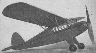
Henry Mayors' "Convertibile Ski Job" (March 1937
F.A.) is another excellent design for outdoor commercial types.
We already know that to get the maximum motor endurance, the
rubber motor should weigh 2/3 the weight of the complete model.
Let us make this item number one below the "object" list of our
endurance problem. Next we want our model to climb as high as possible.
This comes under maximum altitude attainable which we know is: Max.
Alt. = Motor endurance X Climbing rate. Item number one tells us
about motor endurance. Therefore, all we need to get the maximum
altitude is the climbing rate. We determine the climbing rate thusly:
Climbing rate = ) Pexc. x 30.000) / Weight Pexc. (power excess)
is the difference between the power required to fly the model in
level flight and the power available at the propeller. Multiply
this by the 30,000 constant and divide by the weight of the model
and the result will be the climbing rate. It again becomes evident
that the less resistance the model has the more power will be available
for power excess. Thus we have item number two for our endurance
problem.
Our next consideration, the sinking speed of the model, is determined
by multiplying the speed of our model by the gliding angle. These
factors are controlled by the resistance of the model and the general
efficiency of the whole plane. Thus we can readily see that the
primary requirements for endurance are:
1. Proper rubber to model weight ratio.
2.Minimum of drag.
3.General efficiency of plane:
Which includes proper arrangement of surfaces and setting of
angles.
We have thus far discussed the model from purely a physical viewpoint.
It remains for us now to investigate the aerodynamics involved.
When a body of any shape is wholly immersed, and subjected to
motion, in a fluid medium, its resistance to motion will depend
upon the following factors. 1. The speed of the body, 2. the shape
of the body, 3. the size of the body, and 4. the nature of the fluid
medium.
Dealing with these factors it is well known that the resistance
of a body in air increases as the speed increases. The mathematical
expression for the resistance includes each of these factors, and
is expressed thusly: R = K V2 where K is a constant depending
on the shape of the Body. This relation holds true for windspeeds
of 20 m.p.h. and over. However, since most rubber models fly under
this speed, this law, by which all the airfoils used by model builders
have been designed, does not hold true with the model builder. Obviously
then our first consideration for endurance is to obtain an airfoil
that will give us the greatest possible lift with the least drag
in the range concerned. The speed at which most models fly ranges
from zero to fifteen m.p.h. A few airfoils embodying these requirements
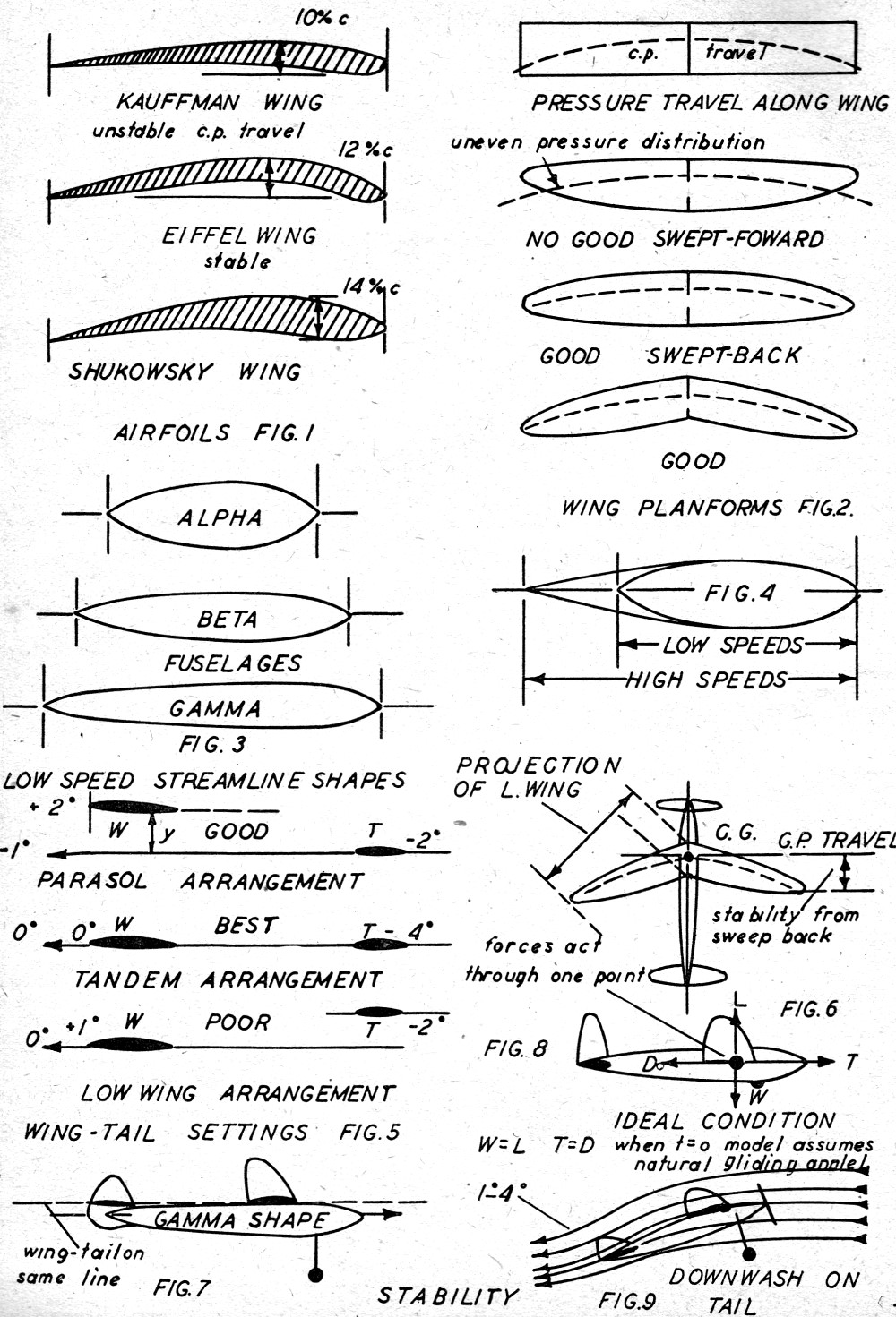
are shown in Fig. 1. It has also been found through wind tunnel
tests that the tear drop is not the most efficient shape at low
air speeds, as so commonly believed. When designing fuselages abide
by the shapes shown in Fig. 3.
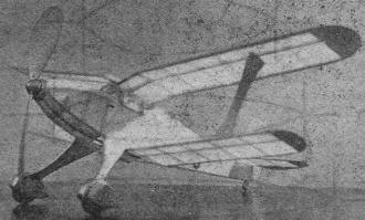
The "Kiltie Gull," also by Mayors (February 1939
F.A.) displays streamlining with little frontal area. General design
rates A-1.
The importance of streamlining every part of the model cannot
be over-emphasized. But we must not duplicate real airplane streamlining
for we are only working under low speed conditions. High speed streamlining,
necessitating greater fineness ratio, results in longer and heavier
structures. See Fig. 4.
Thus we can understand the model builders' complaint that streamlined
models were unnecessarily heavy. Their models were streamlined after
real airplanes with the obvious result of overweight.
We can classify the resistance of a model into three divisions:
1. Fineness ratio or shape of the body.
2. Surface or skin friction.
3. The general arrangement of surfaces which is known as
the mutual interference.
Most model builders employ the first and last considerations
effectively, but they underestimate the importance of skin friction.
It has been shown by wind tunnel tests that at least 50% of the
total drag of a body under low wind speeds is due to skin friction.
Minute as it seems, we should not let the model wings, and tail
go unsanded. In fact, every part of the model should be waxed to
the point where it glistens.
Let's turn to what is probably the most important phase of model
designing; the arrangement of forces necessary to produce stability.
If we are to attain our endurance goal, we must design our model
so that it consumes all the power available for climb, and yet retain
the gliding characteristics of a sea-gull. Yes, a difficult combination,
but far from impossible. What we must embody within the design is
a powerful combination of lateral, longitudinal and directional
stability. Investigating each, keeping in mind the goal of maximum
climb and maximum glide. First, our model must contain the following:
1. 2 degrees positive incidence in the wing.
2. Wash-out in wing tips.
3. 2 degrees negative incidence on tail.
4. Right and negative thrust on motor.
5. An adjustable tab on the rudder.
With above and proper arrangement of areas we may reach our goal.

Chart of Free Flight Endurance Airfoils, Planforms,
and Flight Adjustments
Posted August 15, 2015
|