I remember receiving my copy of the September 1973 issue of
American Aircraft
Modeler magazine with the photo of the
Sparrow RPV
on the cover. Such a thing was a big deal back in the day. It was
ground-breaking research and development for small RPVs with real-time video
feedback. There was no GPS to help guide the
airplane and flight stabilization was relatively crude. Well-known R/C modeler
and former AMA president
Don Lowe was on the team. "On Monday, Oct 19th Jim
Dalton and Doug Erhardt delivered a new aircraft to the museum, the Sparrow.
Offered by Jim and accepted by the Museum's Acquisition committee, the aircraft
was designed by Raymond Fredette of the Flight Dynamics Laboratory at
Wright-Patterson Air Force Base in the early 1970s..."
Website visitor David M. wrote
to request this article Sparrow RPV, from the September 1973 edition of American
Aircraft Modeler. The Sparrow was the forerunner to many of the world's modern marvels
of technology in the RPV - now called Unmanned Aerial Vehicles (UAV) - world. Why
"unmanned" rather than "remotely piloted"? Simple, it is because many of the aircraft
now fly autonomously for at least a segment of their missions; therefore, it is
its own pilot. Author Dave Scully could not have known at the time he was describing
the future of everything from mass produced large, prefabricated aircraft, high
displacement engines, 14"-plus propellers, and the installation of wireless sensors
in aircraft. A large (80" and 160" wingspans), heavy (25 lbs. & 200 lbs.), with
2 hp & 12 hp engines, and 16" props was a novelty back in the day, and was mostly
the realm of government-financed research projects and wealthy private modelers.
Today, dozens of manufacturers offer affordable (not by me, though) giant scale
models and a complete line of accessories. Use of more than 5 servos was virtually
unheard of, but now even some sailplanes have 6 or more. For less than $200, you
can now buy a complete wireless video system, radios include remote telemetry data
on system health as well as airspeed, altitude, engine or battery temperature, and
much more. Hobby Lobby was selling a complete wireless system (PilotView FPV 2400) for a
few hundred dollars until the FCC filed a violation order. Any day now I expect
to see a model scale synthetic aperture radar (SAR) system for 3-D terrain mapping
and remote infrared (IR) night vision. The military already has it.
Say, why didn't I get to work on this kind of a cool project when I was in the
USAF, like MSgt. Scully here?
Sparrow
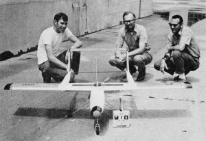
Principal members of the Teleplane Team are (left to right):
Dave Scully, Don Lowe, and Jim Cline.
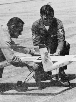
Sparrow flies with 24 lb. of video equipment and both Ross 4
and Ross 6 cylinder engines. Here Jim Cline puts the starter to it while Dave Scully
holds on.

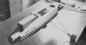
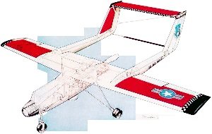
This colorful plane waits patiently for flight duty. Construction
utilizes mostly fiber-glass and foam/plywood flying surfaces.
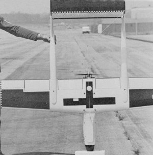
Top view shows that a great deal of flap area is available for
slow flight work.
Underside, Ross 4 installed at this time. Spreader bar at tail
is streamlined K&S tubing. Rudder linkage passes through it.
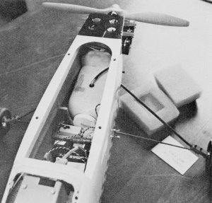
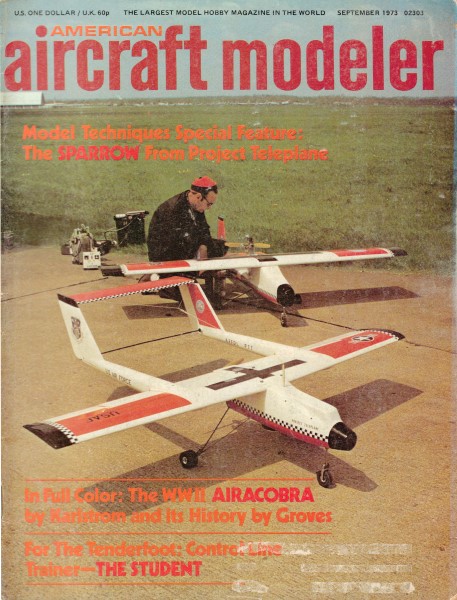
There's plenty of room in here for equipment installation. Remember,
it must have a payload for flight to keep the CG forward.
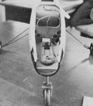
One servo pictured here is just for steering the nose gear. A
parallel servo handles the rudders.
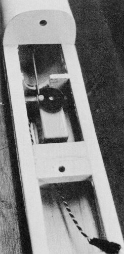
The pod hatch removed. That Sony TV camera, in its present location,
could handle weather sampling equipment, radar, a laser, etc.
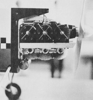
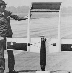
Lighting all the plugs at once is easy with the springs seen
here. Engine runs both ways, so a pusher prop is not required. Note sump tank at
firewall.
This RPV is more than an interesting project designed for carrying movie
cameras. It is a multi-purpose research or practical application industrial tool
for carrying substantial payloads in a pusher configuration.
by Dave Scully
Sparrow is a special purpose, remote-controlled model being used by the Air Force
at Wright-Patterson Air Force Base to develop RPV (Remote Piloted Vehicle) technology.
This design represents the groundwork of a concept which may someday see the RPV
emerge as an operational weapons system performing missions which are presently
relegated to manned aircraft.
The advantages of such a concept are numerous. Aircraft no longer limited by
man's physical tolerances would be more maneuverable in air combat situations. Hazardous
missions such as low level recon, weapons delivery, and target marking could be
performed by expendable RPVs. Other advantages include a high degree of mobility,
lower development, production, and maintenance costs.
What role does the RPV play in civilian aviation? Remote-controlled models have
been used for some time as an aid in the development of full-scale aircraft, and
more recently as a means' of obtaining special aerial sequences for the film industry.
Universities and re-search agencies have utilized radio-controlled models for various
projects, among which the development of the Hill autopilot is probably the best
known.
Tomorrow's need for special purpose RPVs may exist in such areas as weather sampling,
high altitude research, and environmental control. We will undoubtedly see a growth
in engine development, control systems, and RPV design to meet these future requirements.
Sparrow is one design which could be adapted for use where requirements dictate
a model capable of carrying a substantial payload or a model suitable for aerial
photography.
Sparrow was designed by a team headed by Aeronautical Engineer Raymond Fredette
of the Flight Dynamics Laboratory at Wright-Patterson Air Force Base, Ohio. Mission
requirements for the full-size vehicle called for an aircraft which would carry
up to 100 lb. of payload and cruise in the range of 80 to 100 mph. Design considerations
included an unobstructed forward view for video experiments, and the capability
of accepting a variety of payload configurations. As a result, the design presented
evolved as the most desirable configuration for planned remote piloting experiments.
The model presented in this article is actually a half-size version of the Fredette
design, which was built as an engineering aid, and proved to be extremely useful
as a low-cost method of elevating performance, and developing fabrication techniques
relative to its full-scale counterpart. A Sony video system was later installed,
and basic piloting experiments via video were performed with excellent results.
Sparrow exceeded our expectations in its flight characteristics, and its suitability
as a test bed for future experiments. Apart from a lack of readily available engines
for models of this size, I can honestly say that we encountered no major problems,
either in constructing or in flying Sparrow. Our plane has flown well with a Ross
4 and even better with the Ross 6.
A model of this design as published, or possibly as an enlarged version, might
be useful to a modeler interested in performing experiments of his own, or in taking
in-flight movies. As I mentioned before, inexpensive available engines pose a problem
and possible alternatives might consist of using two engines (60s or 80s) mounted
on the booms as in the P-38. Little would be gained by shrinking the design, as
the wing loading would increase with a corresponding decrease in payload capability.
Generally speaking, the larger the model (wing area), the more efficient the design
will be in terms of its payload percentage.
Fig. 1 shows a comparison of the half-scale to the full-scale that may be helpful
to those who would want to determine their own requirements for an enlarged model.
| |
Figure 1 |
|
|
Half-Scale |
Full-Scale |
| Wingspan |
80" |
160" |
| Engine |
2 hp |
12 hp |
| Wing area |
7.5 sq. ft. |
30.0 sq. ft. |
| Wing loading |
3 lbs. sq. ft. |
7 lb. sq. ft. |
| Gross wt. |
25 lb. |
200+ lb. |
| Payload |
10 lb. |
100+ lb. |
If a five-lb. movie camera was the desired payload, two 60s on the half-scale
would probably be sufficient to achieve good takeoff and flight performance.
Construction
A very general description of the techniques used in fabricating this model are
all that will be described, as it is anticipated that the experienced builder will
adapt this design to his own proven methods of construction. Suggested changes for
a simplified method of building this model would be to use a balsa wood box construction
for the pod and the booms, and the more conventional method of control surface found
on most RC models. The flaps could be eliminated on the half-size version, as we
found we could land quite slowly without them. However, for larger models or flying
fields that require steep approaches and the slowest possible touchdown, by all
means include the flaps.
Pod - Fiberglass construction was utilized to gain maximum internal space to
accommodate payload requirements consistent with minimum cross sectional area. As
I mentioned, balsa wood construction could easily be substituted and past construction
articles on scale models of the OV-10A would be a good source of ideas, however
I leave this to the ingenuity of the readers. Fiberglass construction is not really
difficult; the following is a brief description of the steps we used in constructing
the fiberglass pod. Experiment with small parts such as wheel pants, cowls, etc.
before tackling a complete fuselage. Once you learn the process, it's hard to go
back to the glue and pin method of construction in terms of the savings in cost
and time.
The original pattern was carved from urethane foam (Pro Foam would be suitable
for this purpose) and sealed with K& B coating resin. The resin is sanded and
reapplied as necessary to obtain a smooth surface. The pattern was designed to split
along the thrust line and the two halves were mounted on plywood boards. The pattern
is then coated with a good paste wax and buffed thoroughly. A coat of vinyl separator
is applied by brush or spray and allowed to dry. The mold is constructed by brushing
on a gel coat (commercially available) to the prepared pattern and allowing it to
set up. The mold is then built up to the required thickness (1/8" is sufficient)
with layers of fiberglass mat saturated with polyester resin. The mold is allowed
to cure at least 48 hours before removing it from the pattern and is then washed
with water to remove the separator. The steps involved in making the finished pod
are the same as for the mold except that fiberglass cloth is used instead of mat.
The pod on Sparrow is laid up with one layer of seven-oz. cloth and a doubler of
two-oz. cloth. The rear of the pod is reinforced with seven-oz. cloth to handle
engine vibration. The excess cloth above the parting line of the mold can be trimmed
off with a sharp knife just after the resin sets up (about 30 min.). The pod halves
are left in the molds at least 24 hours and then removed, washed and held together
with masking tape. They are then joined with a one-in. strip of cloth applied to
the inside with polyester resin. Plywood formers are installed using a putty made
of polyester resin and silica powder as an adhesive. The forward hatch is cut out
last with a razor saw and a flange installed to accept hold-down screws.
Wing - The wing sections used are NACA 23012 at the root and NACA 4412 at the
tip. The leading edge radius has been reduced and the forward coordinates have been
modified to allow the wing to operate within a Reynolds Number range of .88 to 1.5.
Standard foam wing construction techniques are used with the following exceptions.
Access tunnels are cut through the cores using the guides pro-vided on the wing
templates. The wing is covered with 1/64th plywood using Bestine rubber cement as
an adhesive on foam-to-wood bonds and Formula 2 epoxy on wood-to-wood bonds.
If the wing templates are lined up on the datum line, you will notice that the
tip has effective wash out (e.q., the tip has negative incidence as compared to
the root section and insures that the tip will stall last). This factor contributes
to the outstanding slow flight characteristics of Sparrow and it is important to
insure that the wing is built accurately. We found it advantageous to cover the
wing in the same manner as a Formula I racer. Each wing panel was cut from a separate
foam block which was parted to form an upper and a lower mold; the wing core was
then placed in these forms while wrapping. Since the wing has no dihedral, the wing
panels were joined together using the lower foam blocks as an alignment guide. The
flaps are connected via a fiberglass arrow shaft pivoting on plywood bearings. The
flaps are glued to the shaft with epoxy and pinned with toothpicks. The ailerons
are connected using 90° bellcranks and 3/16" dowel pushrods running through the
access tunnels pro-vided in the wing. The extension harness for the boom servos
are also routed through these tunnels. The wing center section is reinforced with
fiberglass cloth and epoxy after joining.
Booms-The booms are fabricated from Styrofoam and covered with 1/64th plywood
with the exception of the section at the wing saddle, which is built up and sheeted
with 1/8" balsa plank. A 1/16" balsa spline is glued down the top center of the
boom and a 1/16" plywood plate is installed below the vertical stabilizer to add
rigidity and serve as a mounting plate for the elevator bellcrank. The 1/64th plywood
covering is dampened with a mixture of ammonia and water to prevent splitting while
wrapping and is bonded to the foam with rubber cement. The plywood is lapped on
top of the boom and the seam covered with a 1/2" strip of 1/64th plywood secured
with epoxy. The forward section of the boom is rein-forced with fiberglass cloth
and epoxy.
Tail Surfaces - The foam and balsa surfaces are constructed in much the same
manner as the wing. Note that the left vertical stabilizer requires an access tunnel
for the elevator linkage. The rudders are mechanically interconnected using a nylon
linkage housed In a strut made from K&S streamline tubing.

Tail boom at wing saddle shows location of elevator servo here,
rudder servo in other boom. This part of boom is balsa; rear part is fiberglass.

Bottom of wing shows receiver location, flap servo and aileron
servo.
Engine and Miscellaneous - Sparrow has been flown with both the Northfield Ross
4 cylinder and 6 cylinder engines. The Ross was chosen primarily to reduce vibration
effect on the video equipment and proved to be satisfactory, although a bit expensive
for the Sunday flier. The Ross was not designed to be flown as a pusher but since
it is a reed valve engine it can be operated in either direction. To date our Ross
engines have been operated in reverse rotation using 14/6 and 16/6 tractor props
respectively without suffering any ill effects.
Woodcraft Mfg. was the source of our props and I believe they can supply the
larger props in either the tractor or pusher configuration.
The fuel systems we use on our project aircraft are strictly homemade (Jim Cline
specials) and the normal procedure is to find a container that will fill the available
space. In this case we used a plastic aspirin bottle which was modified for fuel
lines by using grommets (similar to the Tatone stick-a-tube method) to seal the
tubing where they enter the tank. Sparrow's fuel system is not designed for prolonged
inverted flight and it proved satisfactory to run a feed line from the lower rear
of the tank and a vent line from the top of the tank to complete the system. With
the Ross engines it proved necessary to run a larger than normal feed line (about
1/4" I D) to the engine and cobb up a brass tubing manifold to feed the individual
carburetors.
The main landing gear strut was bent from 1/4" drill rod and re-tempered, however,
two pieces of 5/32" music wire bound together with brass wire and soldered would
do just as well. The tandem wheels (three-in. Du-Bro slicks) on the main gear have
worked well in the absence of larger commercially avail-able wheels.
Finishing - The model was completed using K&B products. All wood was sealed
with coating resin and the model primed and finished with SuperPoxy paint.
Checkout - Our ground checks prior to flying consisted of the following. CG located
between 21.5" and 24" aft of the nose. Control deflections: ailerons 150, rudder
300, elevator 250 up, 300 down, and flaps 00-450 range. The radio was given a thorough
range check both with the engine running and static. It was found that a capacitor
(Erie Red Cap PN 8101-050-651-10ZM) had to be added on the Pro Line receiver to
eliminate problems caused by the long leads to the boom servos. One cap was added
on each channel between the decoder output and ground and the receiver was then
retuned. We then went one step further and secured the aircraft to the top of a
station wagon and charged up and down the runway checking for flutter and the odd
chance that we could get a 4000-lb. payload off the ground. Finally, deciding that
there was nothing left to tighten, adjust, or paint, the batteries were charged
and we headed for the flight line.
Flying
Takeoffs with a gross weight in excess of 25 lb. (ten-lb. payload) requires a
long ground roll. With 100 of flaps lowered, the model accelerates approximately
150 ft. before the nose wheel is lifted off, about 15 feet later the plane is airborne
and climbs out quite rapidly. In flight, Sparrow is stable and relatively easy to
fly. I'm not going to "put you on" and say that the design will fly the entire FAI
pattern with a sick engine. In fact, with a three-lb. wing loading on a model of
this size it should fly like a nervous brick, but the point is, it doesn't. Sparrow's
flying and handling characteristics compare more closely to a light aircraft than
to a model, although forgiving in most circumstances, she won't tolerate rough handling
and is definitely a model for the experienced flier. The control response is positive
without being touchy and stalls are gentle and predictable. (You can almost feel
the controls get mushy.) With full flaps and down trim the plane can be slowed to
a crawl with no indications of a stall.
I can't give much of a comparison as to the flying qualities at different weights
since Sparrow has to carry payload or ballast to balance properly. The lightest
weight the model was flown at was 22.5 lb. on the first test flight.
The only aerobatics that have been performed to date have been rolls and one
short field landing. That is to say, I landed about 50 ft. short of a long field
when I found you can't stretch a glide with a dead engine. The airplane suffered
only minor damage but my pride suffered more by missing a 7000-ft. runway with a
seven-ft. model.
On landing, Sparrow's sink rate is somewhat higher than one is used to (as you
might have gathered), but touch-down is quite slow and, as I stated before, flaps
have not been found necessary as a landing aid on this size model.
I would be interested in hearing from groups or individuals who would benefit
from a special purpose model such as described in this article. Let me know the
payload requirements and purpose of its use. Sufficient interest in this area might
warrant production by a kit manufacturer of fiberglass and foam components that
would satisfy a variety of needs.
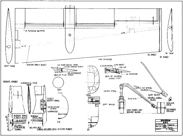
Sparrow RPV Plans, Plan Sheet #1
<click for larger version>
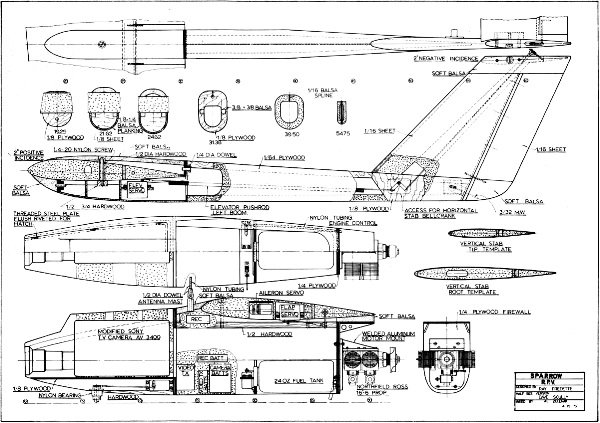
Sparrow RPV Plans, Plan Sheet #2
<click for larger version>
Notice:
The AMA Plans Service offers a
full-size version of many of the plans show here at a very reasonable cost. They
will scale the plans any size for you. It is always best to buy printed plans because
my scanner versions often have distortions that can cause parts to fit poorly. Purchasing
plans also help to support the operation of the
Academy of Model Aeronautics - the #1
advocate for model aviation throughout the world. If the AMA no longer has this
plan on file, I will be glad to send you my higher resolution version.
Try my Scale Calculator for
Model Airplane Plans.
Posted October 31, 2022
(updated from original post
on 4/25/2011
|