|
It would be
interesting to do a side-by-side comparison on what was considered engineered control
line stunt model airplane design in 1957, when this article was written, to what
is today considered to be optimal design criteria. I am trying to get back into
control line stunt flying and have one model built currently, the
Enterprise-E.
It has been flown a few times and is (was) extremely sensitive on the controls when
set up per the plans. A little bit of control handle movements resulted in a huge
amount of both elevator and flap deflection. Fortunately, access to the flap control
horn is available through the removable top fuselage hatch, so I was able to relocate
the pushrod from the bellcrank to the flap horn, and then from the flap horn to
the elevator control horn. Overall throws are a little more than half what they
were, so once the weather clears, I'll try the new configurations. The information
in this article will be helpful when working out how to set up the
Shark 15 control line
model I am building right now. The
Enterprise-E
is equivalent to a 35-40-size glow fuel stunter and has a built-up fuselage. The
Shark 15 has a profile
fuselage and a completely accessible control setup, so I plan to leave the
Enterprise-E
hanging safely on the wall whilst the Shark 15 re-introduces me to the fine
art of control line stunt. The
Shark 15, BTW, was my first-ever non-Cox control line model airplane as
a kid, so for the sake of nostalgia I am building one from original plans in a kit
I bought on eBay a while back. It is using a 10-size brushless motor setup rather
than the Fox .15 the original used.
More... About Stunt Theory
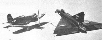
Corsair, left, a Sterling kit with Fox .59 and proportionate
throttle operated from a Roberts Flight Control System. Top 90 mph, low 25 mph.
Sea Dart, right, bit of mystery but sports a spinner.
This is tough going but digging diamonds also is tough. If the long-haired stuff
is too deep, the recap at end will prove worth studying.
by W. F. Netzeband, Jr.
Flaps are a must for the modern stunt ship for several reasons. They increase
the lift when it is most needed, by copious amounts. They allow us to use thinner
airfoils for level flight, which cuts down the possibility of hunting, and decrease
the sensitivity to lift changes caused by wind. One detrimental affect is causing
the center of pressure to move aft when they are depressed, resulting in nose heavy
trim. This is corrected by using larger, more effective elevator action as we will
discuss later. As for size and shape, size depends on wing chord. The author prefers
to start with a wing area and add the flaps to it. The chord of the flap is: CL
= 0.20C, where C is wing chord. Flaps for our wing would be 1.8 inches wide.
It has not proved best to run flaps full span, since they cause excessive wobbling
laterally due to burble and increased lift at the wing tips. Therefore, flaps should
taper in width from root to tip or simply not run full span. Amount of taper is
arbitrary. A criterion for smooth flying is to have the wing tips stall last. With
flaps, an airfoil stalls at lower angles of attack than without; around 8 degrees
compared to 10 degrees with a 12% thick section. By reducing the flap size, and
hence the effect toward the tip, we accomplish this aim.
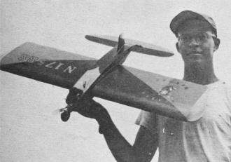
In keeping with the style five years ago, this author's original
used a thick wing section, won a few meets, but not exceptional.
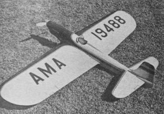
But an 18% section on this Palmer design gave good pattern at
a 60 mph speed, squared well. Span was 52 in. and flaps utilized.
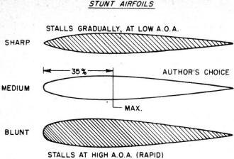
Stunt Airfoils
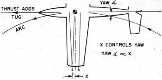
C. G. will align itself along the line of restraining force.
This does not depend on the bellcrank location. Bellcrank should be on C.G. for
least resistance to motion. Note that lines will form an arc due to their drag which
will make actual yaw angle less than if lines were taut. The reference point at
the tip moves toward the line carrying the larger load.
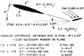
Angular difference between wing & stabilizer = 8° + 2.25°
= 10.25° necessary moment on plane.
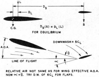
Relative air not the same as for wing effective A.O.A. now α + Θ.
Try D.W. of 6CL for flaps.
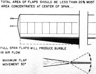
Total area of flaps should be less than 20% most area concentrated
at center of span.
It should be apparent that the closer to the fuselage we develop our center of
lift, the lighter we can build our wing and we are less apt to have tip wobble.
Tapered flaps, tapered or elliptical wings and other tricks are used for this. Maximum
deflection should be 30 degrees and can be as little as 10 degrees. These depend
on several factors which will be brought out gradually. Total area of flaps compared
to wing area should be less than 20% with most of the area concentrated in the center
portions of the span. Distribution of area hasn't appeared to need mathematics yet.
Too many variables are involved.
In order to compare characteristics, total weight is usually treated as weight
per unit area for the wing. This enables us to use data gained in tests. Simply
stated, a heavy airplane with a large wing will turn the same as a light airplane
with a small wing, if their wing loadings are equal. Through experiment and experience
the following are considered the best range of wing loadings for flapped wings and
normal wings: with flaps - 0.05 to 0.10 oz./sq. in.; without flaps -0.05 to 0.07
oz./sq. in.
The 0.10 oz./sq.in. would give a 50-ounce airplane for 500 sq. in. Lower figure
is a minimum practical limit. Some have exceeded this with featherweight combat
ships, but not many.
For the present we are ignoring the flying wing for stunt use. Harold Reinhardt
is the only one, to our knowledge, who has won a big meet in stunt with a wing.
Mr. Reinhardt is also a superb flier. We are studying the possibilities of this
shape, but are not far enough along to make firm decisions. So, the stabilizer is
still required. For those who are in doubt as to why the stabilizer, it does what
its name implies. Stabilizes the wing. Through the elevator it controls the wing's
angle of attack, hence controlling the flight attitude of the airplane. We balance
the airplane ahead of the center of lift and bring the system to equilibrium by
causing the stabilizer to generate a down load. See Figure 3. Most symmetrical airfoils
lift at the 25% location as previously mentioned. Therefore, always locate the CG
forward of this point. When we want to climb we give "up" elevator which increases
the down lift of the stab. The wing then starts to balance this change. It begins
to increase its angle of attack until it balances the stabilizer load. In doing
this, it generates more lift so the airplane seeks an attitude to balance the increased
lift. Our model moves in a circle which we call the loop.
In the formula consider, for the moment, DS as fixed. If we decrease
DL; i.e., move the CG aft, it will take less force from the stab to produce
a given change in lift. As we move the CG forward it takes a larger change in force
to change L. This is the secret of sensitive and coarse control. The other method
is to increase or decrease elevator area or motion. By placing our CG at 10%, or
forward, we get coarse control or large motions of elevator are necessary to cause
changes of attitude. If we balanced right on the 25% line we would find a very sensitive
ship since, theoretically, zero force would move the wing. If we move the CG aft
of the 25% line we must have positive force, or "down" elevator to control the wing.
Free flighters are familiar with this through the use of lifting stabs.
This condition fouls up the control-line ship for two reasons. First, any time
we get a down load on the stab our ship would climb violently, in fact uncontrollably.
Correction results in over correction and usually a splat. Second reason on stunt
ships is the very low AOA in level flight. With aft CG, our stab is now lifting
so wing lift must decrease or we'll climb. So we approach our zero lift angle and
generally pass it, causing a quick dive since our system suddenly becomes way unbalanced.
Again correction causes over-controlling and same end result. We tried this experimentally
using a lifting stab on a team-race design. It proved to be flyable, but not too
controllable, since it wandered up and down on it's own. This balance condition
occurs in far too many cases of stunt and scale models. You recognize any of your
ships here?
By moving the whole stabilizer we can predict the area necessary quite accurately,
since it will operate as a wing. One thing which occurs as the wing's AOA is increased
is a change in the angle of air over the stabilizer, called downwash. This is roughly
5CL or for a CL of 1 the downwash will be 5°. This downwash,
shown in Figure 3, will make the stab more negative. With flaps there doesn't seem
to be much information on downwash, but we suspect it is greater. Downwash must
then be used to calculate stabilizer motions. To predict area we'll assume some
constants, and add that a stab airfoil due to small chord and detrimental airflow
characteristics will stall at around 6.5° and operate at 75% efficiency. Armed
with our data on the average ship with a 16 inch tail moment arm and no flap we
get this: See Figure 4.
Equating WF to SF we find:

For this set-up we will need 10° deflection of our stab. Notice the extremely
small stab here compared to our tremendous combination stab and elevators. In case
any of you got lost in our math, we tossed out things that appear in both sides
of the equation. Reason for small stab is a real sensitive trim. If we balance at
10%, our area would be 65 sq. in. See how important the old CG location is. We have
been working with maximum lift on both wing and stab. If the stab is forced into
a more negative angle, it will stall and lose download. We have then reached our
minimum loop diameter and will probably open up a little. Ever have this happen
to you? It is not the fault of the wing at all. Normal practice is to stay away
from the 6° angle on the stab, but only work it 4.5°. We then have the ability
to stall the wing, but at least we know what's doing it.
You'll notice we worked on a smooth turn in our last go-round. Will this stab
be good enough for a square turn or our old 5-foot radius? We did some mathematical
playing around and found out it will. If we assume our wing can suddenly lift enough
by virtue of flat-plate pressure increase, even though it's stalled, our present
stab is quite capable of doing the job. The sharp turn depends on an abrupt over-controlling
action rather than smooth increase. We more or less kick our wing loose from its
normal attitude and the whole works goes ape. The loss of speed helps too. Anyhow,
mathematically and practically, the stab from the above calculation is alright in
a square turn.
As for the standard set up of elevator and stab, they don't appear too efficient.
We cannot accurately predict their action since at small angles they work as cambered
airfoils and at larger angles as part wing and part deflection plate. We therefore
must always make them too big. With flaps, our center of lift moves aft when depressed,
which means our elevator must be larger than without flaps. So we fall back on an
experimental value of 25% of the wing area and using an elevator chord equal to
stab chord. Structurally the stab-elevator is simpler to build, while the problem
of bearings and linkage make the stabilator or flying tail more difficult. Having
tried one flying tail, we found that it is indeed much more effective than the conventional
setup.
For those who are interested in using a stabilator, would suggest pivot point
on 25% chord so we have an aerodynamically balanced surface. Use a downwash of say
6CL for a flapped wing. Angular difference will tell you how far to move
it both ways from zero. On stab-elevators we've found it best to limit motion to
30° and to adjust CG from test flights for best turns. More motion causes excessive
drag, has-tens the stall of both surfaces and results in large variations in speed
during maneuvers. The author has made close observations of elevator motion in flight
and has found that rarely does the elevator exceed 20° on ships which are trimmed
properly. Those which do, perform stalled maneuvers which are sloppy and definitely
not desirable in stunt.
In considering wing shape we want to get the most work for a given area and still
be able to get it into an automobile. This limits us to about 54 inch spans, unless
you own a station wagon or hearse. The constant-chord wing gives us the largest
wing area for a given set of dimensions, but the losses at the tip plus the tendency
to wobble laterally make it undesirable. The tapered wing takes more work in design
stages and building, while giving fairly good results in action. The elliptical
shape is the ultimate in efficiency, and can be built up by using a few tricks to
simplify layout and construction.
It has proved best to maintain the flap hinges on a straight line for maximum
smoothness of operation, although slight angles can be used if the flaps are connected
with speedometer cable. Good material has already been presented on structures so
we will only say we prefer the "D" tube leading edge because it gives a smooth section.
The profile or the airfoil section is important but not too important. The author
spent much time plotting airfoils the hard way, and comparing them to zip airfoils.
We learned a few things. When drawing up a flapped wing the airfoil should be considered
without flap, leaving the trailing edge thick enough to support the flap. Our own
airfoils have the maximum thickness at 35% and use a medium leading edge radius.
A sham-pointed leading edge will stall very gradually, but at a lower angle of attack
than a blunt leading edge. The blunt airfoil will stall at a greater angle of attack,
hence giving more maximum lift, but it stalls very sharply or sudden-like, which
leads to surprise landings at three-foot altitudes and such. Therefore, the medium
radius.
If you like to plot airfoils, the NACA four-digit streamlines are quite satisfactory.
The NACA report No. 824 has a lot of interesting dope for those of your who want
to delve deeper into this subject. We would recommend plotting a few airfoils to
get used to their characteristics and then branching out and playing around. It's
more fun that way.
We've worked over the CG location pretty thoroughly already, but want to remind
everyone that it's important. Much has been said pro and con about moment arms,
long and short. Either can be made to work well if the CG is located properly and
the stabilizer is of proper size to do its job. When starting a design from scratch,
the CG location must be assumed in order to have something to base figures on. It
must then be built into the model with a minimum of ballast which is only dead weight.
In general, the long nose moment arm helps here. Weight in the aft end of the model
must be kept at a minimum and structure should be carefully designed for lightness
as well as strength. Stabilizer and elevator should be built-up rather than solid;
on the larger ship, at least. If using sheet balsa keep thickness between 3/16"
and 5/16" and use light medium-grain wood. Use "C" grain wood if possible.
Watch your painting technique, being careful not to get the rear end heavy while
finishing. Finish your model completely before flying. Most of your dope is added
behind the center of lift, so your CG is moved back. This happened to us once with
disastrous results. Experience alone will better your technique for building the
CG into the proper location. But do not be afraid to add weight if it becomes necessary.
Most of our modern stunt ships are too light anyhow. Think about that one for awhile.
With U-Control we need tight lines to maintain control. There are several ways
to guarantee ourselves enough tug at all times. Most important means, which we have
never seen discussed as such, is the lead out location on the wing tip. Some designers
seem to feel it's the bellcrank location. Not so. The CG will, like a plumb bob,
try to a line itself along the line of centrifugal force, or on a radius of the
circle. The center point of the leadouts becomes the pivot point. Therefore, as
long as the CG is ahead of the theoretical pivot, as per Figure 5, the ship will
yaw outward and give us our tug. As a formula we locate our bellcrank 1/4 of the
way from the leading edge and slope the lines aft 5°. This assures a nose-out
yaw. You could theoretically locate your bellcrank anywhere and not change the yaw
angle, unless real stiff wire is used. Cables have proved to be best anyhow. The
speed boys are finding that leadouts in line with CG give more speed, from decreased
or zero yaw.
While we are in this yawed attitude our fuselage is developing lift in the same
direction as our centrifugal force which aids our tug. Be careful of this however,
because, if excessive, it will cause wobbly turns and otherwise sloppy flying characteristics.
If you plan to fly a slow ship on lines longer than 70 feet, increase the sweep
back of the lines, since the natural bow in the lines will be greater. To get a
rough idea of how your present ship yaws in flight hold it up by the leadouts; with
a good tight grip, naturally, and observe the angle. It is expedient to bring the
leadouts through the tip fairly close together, less than one inch apart. This decreases
the tendency of the ship to change yaw angle as the load is shifted from one line
to the other.
Tug is affected by the bank angle of the ship. If banked into the circle, tug
will be less, since the lift is no longer vertical but into the circle. If outboard
wing rides low, the tug is increased in a like manner. The vertical CG location
has a pronounced effect on the bank angle, so some thought should be given to layout
of the side view. The low wing setup has proved to be the best compromise on this
point. The landing gear balances the upper structure bringing the CG down around
the wing for a fairly neutral setup. This presumes the leadouts are brought through
the wing. We built one combat ship with everything above and below the center line
balanced; and the engine laid on its side. This ship flew perfectly level laterally
and was real nice to handle. Engine offset is very effective in controlling tug,
particularly in overhead eights. Three degrees has been found the best compromise
for this. You will always have your pure centrifugal force in level flight, but
the effect is decreased as you climb on the circle. The forces and analysis of same
are greatly complicated in control line due to operating in a hemispherical flight
path. For the most part, detailed analysis proves little.
Next month we'll prove plenty and get this show all wound up.
|