|
History of Rocketry Development Display Case
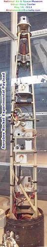
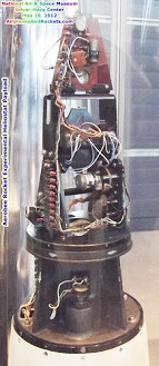
Aerobee Rocket Experimental Payload
This is an instrumentation rack with intact aspect magnetometers and some electronics
that flew on an Aerobee sounding rocket. This rack includes a battery box, junction
box, an optical aspect sensor, and apertures for UV photometers. This artifact is
part of a collection of high-energy detectors from the Naval Research Laboratory.
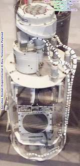
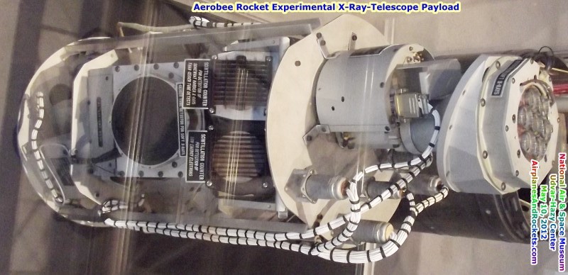
Aerobee Rocket X-Ray Telescope Payload
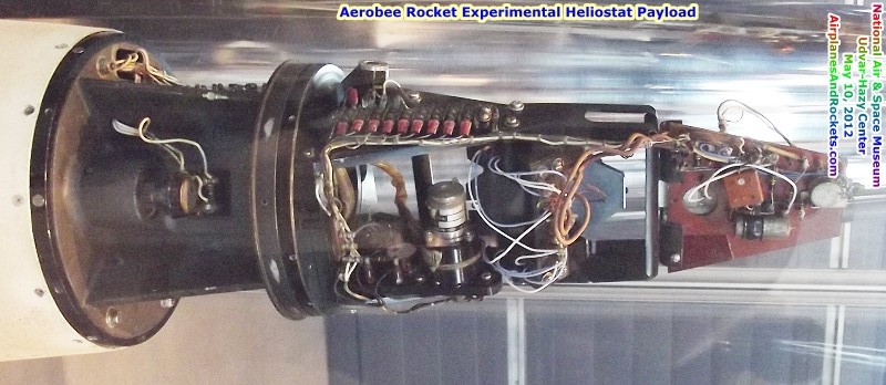
Aerobee Rocket Heliostat Payload
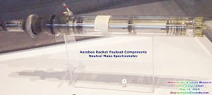
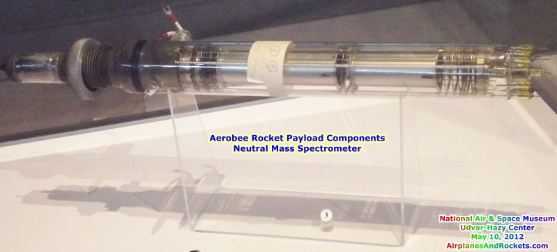
Aerobee Rocket Neutral Mass Spectrometer
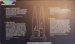
Aerobee Experimental Payload Placard
_small.jpg)
Aerobee Rocket Payload Components
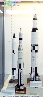
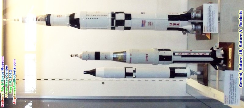
Gemini, Saturn 1B, Saturn V Rockets
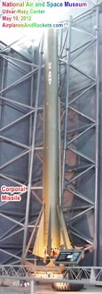
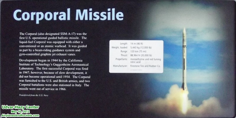
Corporal Missile

Corporal Missile Placard
Manufacturer: Firestone Tire and Rubber CompanyDate: ca. 1950-1958
Country of Origin: United States of America
Dimensions:
Overall: 36 ft. 4 1/2 in. tall x 2 ft. 6 in. diameter, 2960 lb. (1108.71 x 76.2cm,
1342.6kg)
Materials:
Overall, non-ferrous metal, possibly aluminum; steel screws around body; white
plastic inserts in at least two holes around base of missile.
This is the Corporal, America's first operational guided missile. The liquid-propellant
Corporal was equipped with a conventional or atomic warhead and ranged 75 miles.
It was guided by a beam-riding guidance system and gyro-controlled graphite jet
exhaust vanes. Development of the Corporal was begun in 1944 by the California Institute
of Technology's GALCIT (Guggenheim Aeronautical Laboratory, California Institute
of Technology).
It was first successfully Corporal fired in 1947. However, its development was
slow and did not became operational until 1954. The Corporal was furnished to the
U.S. and British Armies and was also stationed in Italy. The Corporal went out of
service in 1966. This missile was donated to the Smithsonian in 1968 by the U.S.
Navy.
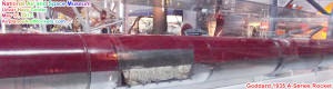
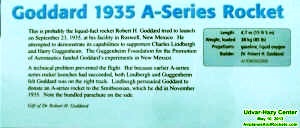
Goddard 1935 A-Series Rocket
Manufacturer: Dr. Robert H. GoddardDate: 1935
Country of Origin: United States of America
Dimensions:
Overall: 15 ft. 4 1/2 in. long x 1 ft. wide x 9 in. diameter x 1 ft. 9 1/2 in.
span (468.63 x 30.48 x 22.86 x 54.61cm)
Materials:
Aluminum skin, thin gauge, along tail section from bottom of fins to bottom of
mid-section. Aluminum skin also on parachute section and nosecone wholly of spun
aluminum except for steel attachment screw. Steel skin (for greater strength and
insulation) below nosecone, over mid-section (over propellant tanks), and around
small section above fins. One steel tube or pipe on each side of rocket, along propellant
section; one smaller diameter copper tube on one side. Steel nozzle and other interior
components. Fabric parachute
This is probably the liquid-fuel rocket Robert H. Goddard tried to launch on
September 23, 1935, at Roswell, New Mexico, in an attempt to demonstrate its capabilities
to supporters Charles Lindbergh and Harry Guggenheim. The Guggenheim Foundation
for the Promotion of Aeronautics funded Goddard's experiments in New Mexico.
A technical problem prevented the flight. But because earlier A-series rocket
launches had succeeded, Lindbergh and Guggenheim felt Goddard was on the right track.
Lindbergh thus persuaded Goddard to donate a complete A-series rocket to the Smithsonian,
which he did in November 1935. This rocket became the first liquid-fuel rocket in
the Smithsonian collections.
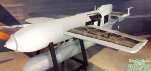
Hs 293 A-1 Missile
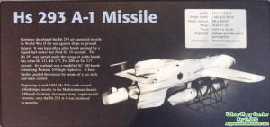
Country of Origin: Germany
Dimensions:
Overall: 10 ft. 4 in. wide x 11 ft. 9 in. deep, 1500 lb. (315 x 358.1cm, 680.4kg)
Other: 11 ft. 9 in. long x 10 ft. 4 in. wing span (358.1 x 315cm)
Materials:
Duralumin alloy, steel
Germany developed the Hs 293 air-launched missile in World War II for use against
ships or ground targets. It was basically a glide bomb assisted by a liquid-fuel
rocket that fired for 10 seconds. The Hs 293 was carried under the wings or in the
bomb bay of an He 111, He 177, Fw 200, or Do 217 aircraft. Its warhead was a modified
SC 500 bomb containing Trialene 105 high explosive. A bombardier guided the missile
by means of a joy stick and radio control.
Beginning in mid-1943, Hs 293s sank several Allied ships, mostly in the Mediterranean
theater. Although Germany developed many experimental versions, only the Hs 293
A-1 was produced in quantity.
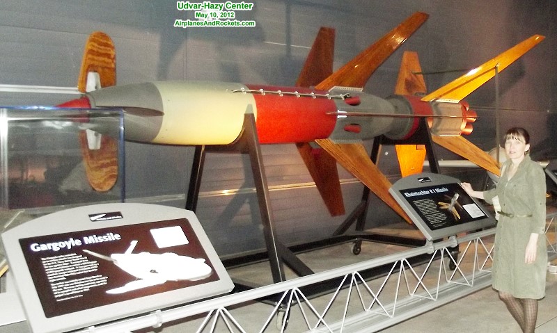
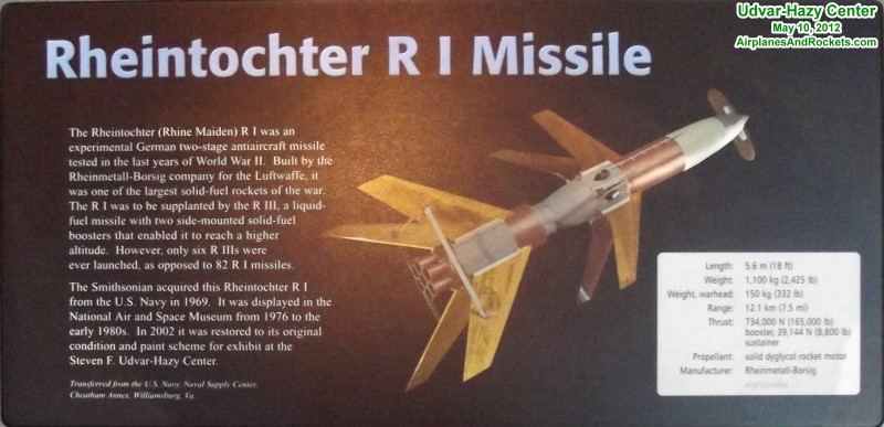
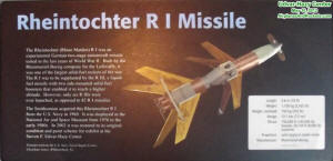
Rheintochter R I Missile
Rheintochter R I Missile Placard
Manufacturer: Rheinmetall-Borsig
Country of Origin: Germany
Dimensions:
Overall: 10 ft. 2 in. wide x 18 ft. long x 1 ft. 8 in. diameter, 2425 lb. (309.88
x 548.64 x 50.8cm, 1100kg)
Materials:
Steel (main body and nozzles of booster stage, main section of sustainer, nose
cap, angle iron booster fin supports); magnesium (nose section, rear section of
sustainer, forward attachment section and fin collar of booster stage); aluminum
(guidance section); varnished wooden fins
The Rheintochter (Rhine Maiden) R I was an experimental German two-stage antiaircraft
missile tested in the last year of World War II. Built by the Rheinmetall-Borsig
company for the Luftwaffe, it was one of the largest solid-fuel rockets of the war.
The R I was to be supplanted by the R III, a liquid-fuel missile with two side-mounted
solid-fuel boosters that enabled it reach a higher altitude. However, only six R
IIIs were ever launched, as opposed to 82 R I missiles.
The Smithsonian acquired this Rheintochter R I from the U.S. Navy in 1969. It
was displayed in the National Air and Space Museum from 1976 to the early 1980s.
In 2002 it was restored to its original condition and paint scheme for exhibit at
the Stephen F. Udvar-Hazy Center.

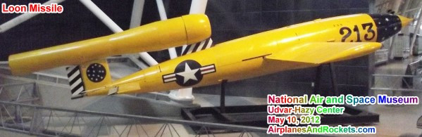
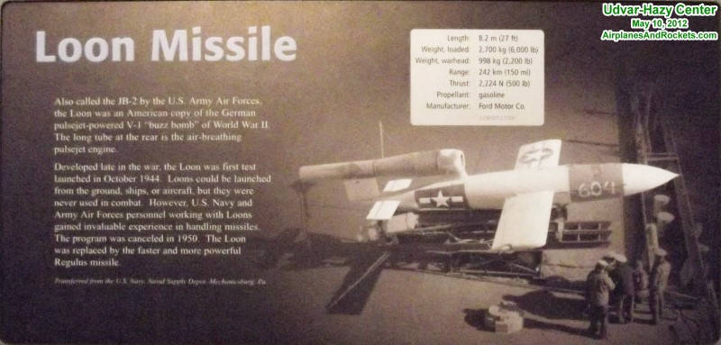
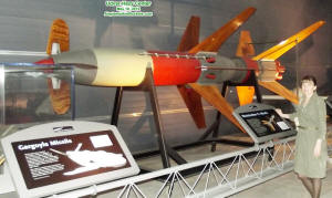
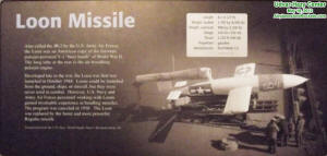
Loon Missile
Loon Missile Placard
Manufacturer: Ford Motor CompanyDate: ca. 1944-1950
Country of Origin: United States of America
Dimensions:
Overall: 27 ft. long x 19 ft. wing span x 2 ft. 8 in. diameter, 1500 lb. (822.96
x 579.12 x 81.28cm, 680.4kg)
Materials:
Overall, steel; propellant and pressurant spheres, steel; pulsejet tube and motor,
steel; piping, aluminum; electrical wires, with transparent plastic insulation;
some wires also with red and gray plastic insulation; nose cap, aluminum; warhead
section, where number is painted, non-ferrous metal, possibly aluminum.
The Loon, also called the JB-2 or KUW-1, was an American copy of the German pulsejet-powered
V-1 or "Buzz Bomb" of World War II. It was designed to carry a 2,200-pound high
explosive warhead to a range of 150 miles and could be launched from the ground,
ships, or aircraft. The air-breathing pulsejet motor is the long tube at the rear.
The development of the Loon came too late for use in World War II, and it was
not used in combat. However, it provided invaluable experience to U.S. Navy and
Army Air Force (and later, Air Force) personnel in the handling of missiles. The
Loon was cancelled in 1950. This object was donated to the Smithsonian in 1965 by
the U.S. Naval Supply Center.
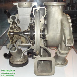
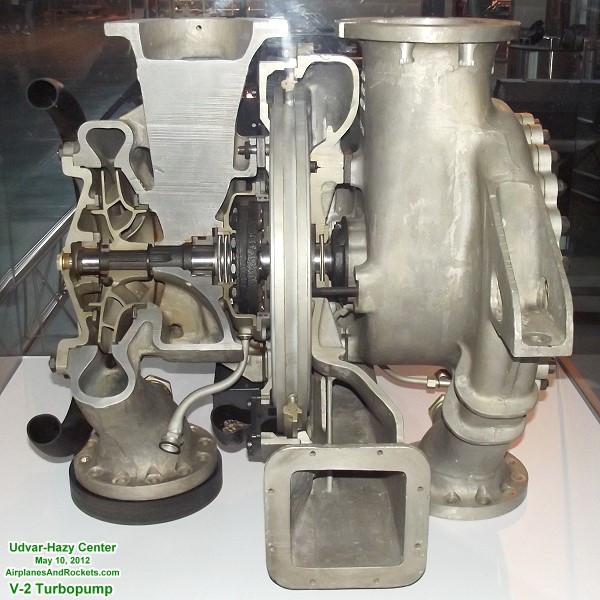
V-2 Rocket Turbo Pump Cut-Away

V-2 Rocket Turbo Pump Placard
Manufacturer: WUMAG, Abteilung MaschinenbauCountry of Origin: Germany
Dimensions:
Overall: 2 ft. 8 in. tall x 2 ft. 5 in. wide x 2 ft. 4 in. deep (81.28 x 73.66
x 71.12cm)
Materials:
Steel, aluminum, rubber and leather seals
The V-2 rocket-engine turbopump drew the propellants--liquid oxygen and water
alcohol--from the missile's tanks and injected them under pressure into the combustion
chamber. The V-2 motor was not only the world's first large liquid-propellant rocket
engine, it was also the first large rocket engine to use a turbo pump, following
on earlier experiments by the German Army rocket group under Wernher von Braun.
This pump moved nearly 9,000 kg (20,000 lb) of alcohol and liquid oxygen from the
tanks to the combustion chamber during the 60-second burning time. Driving the turbine
wheels in the center of the pump were exhaust gases from a steam generator, which
catalyzed hydrogen peroxide into superheated steam and oxygen. The turbine wheels
in turn powered the pump impellers for the two propellants.
This artifact is cutaway to show its internal mechanisms. NASA Marshall Space
Flight Center transferred it to the Smithsonian in 1975.
|

History of Flight Mural
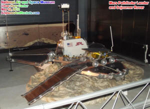
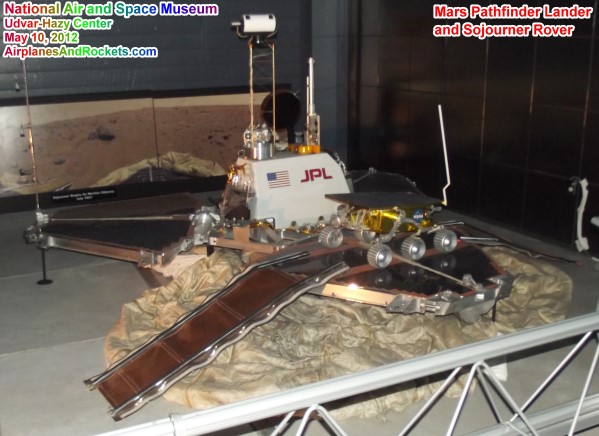
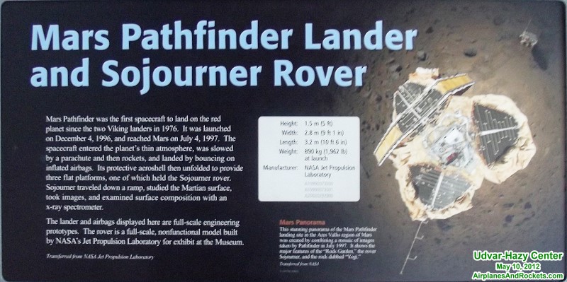
Mars Pathfinder Lander & Sojourner Rover
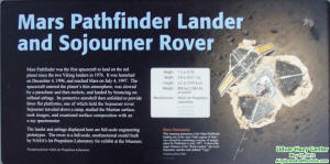
Mars Pathfinder Lander & Sojourner Rover placard
Mars Pathfinder Lander:
Dimensions:
Overall: 5 ft. tall x 9 ft. 1 in. wide x 10 ft. 6 in. deep (152.4 x 276.9 x 320cm)
Materials:
Mixed metals, electronics, optics
Mars Pathfinder was the first spacecraft to land on the surface of the red planet
since the Viking mission in 1976. The artifact is a full-scale engineering prototype
for a spacecraft that was launched on December 4, 1996. On reaching Mars on July
4, 1997, the spacecraft entered the planet's thin atmosphere, was slowed by a parachute
and then rockets, and then landed by bouncing on inflated airbags. The protective
aeroshell then unfolded to provide the three flat platforms, one of which held a
rover (Sojourner).
Pathfinder had a TV camera and scientific instruments to gather scientific data
on the martian atmosphere and weather, as well as solar cells to provide power and
communications. The lander operated for over 90 days, during which it relayed 2.3
gigabits of data including that gathered by Sojourner. Some of this data suggest
the presence of large amounts of water on Mars in the distant past. The spacecraft
as well as the prototype were designed and built by JPL for NASA's office of Space
Science.
Sojourner Rover:
Dimensions: Overall: 1 ft. 11 in. long x 1 ft. 5 in. wide x 2 ft. 8 in. tall,
60 lb. (58.42 x 43.2 x 81.3cm, 27.2kg)
Materials: Plastic, metals, composites, rubber.
The Mars Pathfinder (MPF) spacecraft consisted of a stationary lander and a separate
rover called Sojourner. The rover rested on one of the three MPF solar panels that
were folded over the spacecraft during launch and interplanetary cruise. MPF entered
the Martian atmosphere directly on July 4, 1997 traveling at nearly 7,300 m/s. The
entry vehicle's heat shield slowed the spacecraft to 400 m/s in about 160 seconds
before deployment of the parachute and airbags. The MPF landing site was near the
mouth of Ares Valles, a large outwash plain from one of the largest outflow channel
complexes on Mars at 19.33° N, 33.55° W.
After landing, two ramps were unfurled from the solar panel where the rover was
mounted. The rover was then deployed down one of these ramps where it proceeded
to take close-up images of the surface using two color cameras on the front and
a black and white camera on the rear. The rover also contained a rear-mounted Alpha
Proto X-ray Spectrometer that provided bulk elemental composition data on surface
soils and rocks. In addition, the stubby wheels of the rover provided information
about the physical characteristics of the surface soil and rocks. Images were taken
and experiments performed by the lander and rover until September 27, 1997, when
communications were lost with the lander. However, because communications with the
rover were relayed through the lander, the communications lost brought an end of
the mission for the rover as well.
This spacecraft is a full-scale model that was built by the Jet Propulsion Laboratory
for the National Air and Space Museum. The rocker-bogie, wheels and frame are constructed
of aluminum and are similar to the actual flight vehicle. However, the scientific
navigation, and communication instruments are made of resin and do not possess all
of the detail of the originals. This model was displayed in the "Where Next, Columbus"
gallery from 1992 to 2002.

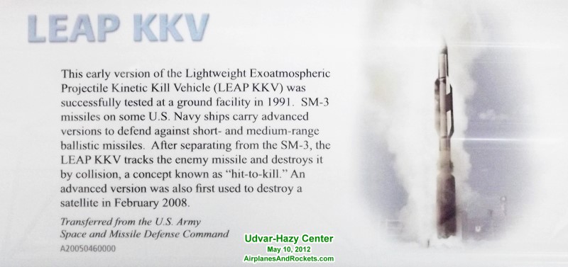
LEAP KKV Placard
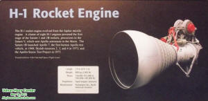
H-1 Rocket Engine Placard
Dimensions: Overall: 5 ft. 3/8 in. wide x 6 ft. 1 1/4 in. long x 3 ft. 11 in. diameter,
2000 lb. (153.42 x 186.06 x 119.38cm, 907.2kg)
Materials: Chamber and nozzle coolant passages 347 stainless steel. Propellant
tanks, lines, and valves, stainless steel. Pumps, aluminum alloys; turbine, Hastealloy.
Injector, OHFC copper and 347 stainless steel. Combustion chamber made of 292 stainless
steel tubes. The assembly, except for inlet manifold, was furnaced brazed with gold
brazing alloy. Injectors, furnaced brazed.
This is the H-1 liquid-fuel rocket engine, the first stage powerplant for the
Saturn 1 and Saturn 1B launch vehicles, the precursors to the Saturn V that took
men to the Moon in the Apollo program. The Saturn 1 and Saturn 1B were each fitted
with eight H-1 engines in their first stages. The engine was developed and built
by the Rocketdyne Division of North American Aviation, Inc., and used RP-1 (kerosene)
and liquid oxygen. The H-1 evolved from the Jupiter missile engine.
The version of the engine shown here developed about 188,000 lbs of thrust. The
Saturn 1B launched Apollo 7 in 1968, Skylab missions in 1973, and the Apollo-Soyuz
Test Project in 1975. This engine was donated in 1968 to the Smithsonian by Rocketdyne.
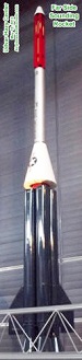
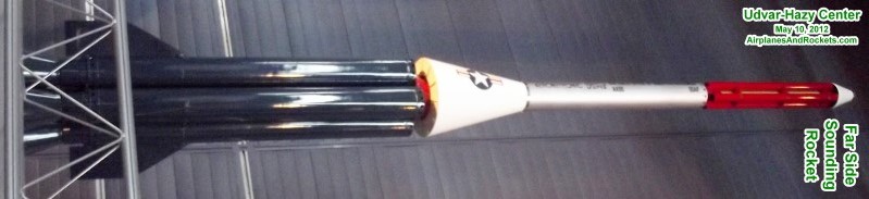
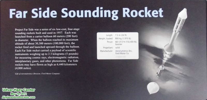
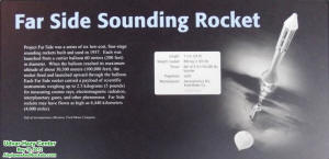
Far Side Sounding Rocket
Far Side Sounding Rocket Placard
Dimensions: Other: 1 ft. 8 in. diameter x 23 ft. 12 in. tall (50.8 x 731.5cm)
Materials: Primarily aluminum, with some steel
Project Far Side was a series of six low-cost, all-solid-fuel, four-stage, balloon-launched
sounding rockets, each launched from a carrier 200 foot (62 m) diameter balloon,
and built and used in 1957. When each balloon reached its maximum altitude of about
100,000 feet (30,480 m), the rockets fired through the balloon.
Each Far Side rocket carried a scientific payload of three to five pounds (1.4-2.3
kg) of instruments for measuring cosmic rays, electromagnetic radiations, interplanetary
gases, and other phenomena. The maximum altitude reached by the Far Side rockets
may have been 4,000 miles (6,440 km).
This object was donated to the Smithsonian in 1965 by the Aeronutronics Division
of the Ford Motor Co.

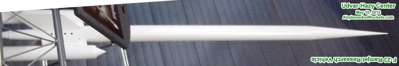
F-23 Ramjet Research Vehicle
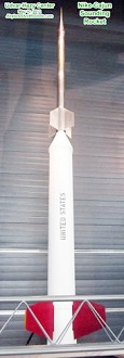
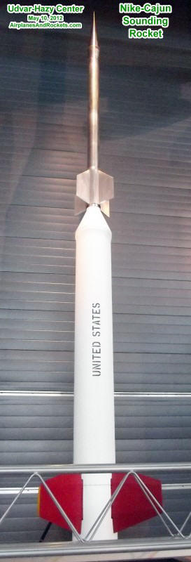
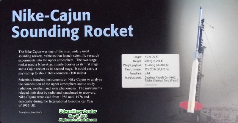
Nike-Cajun Sounding Rocket
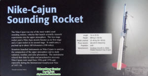
Nike-Cajun Sounding Rocket Placard

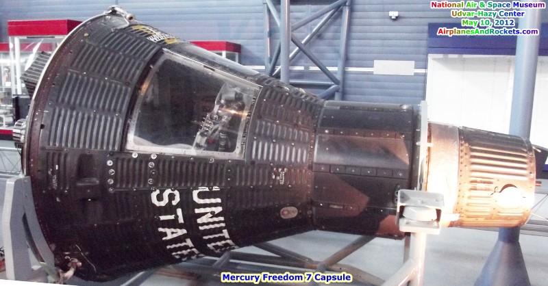
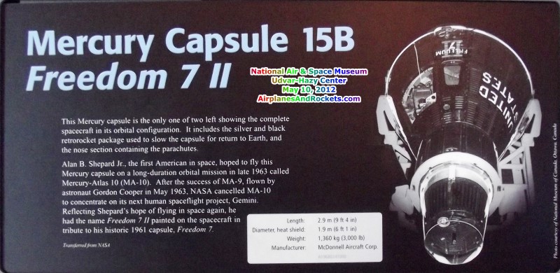
Mercury Capsule 15B - Freedom 7 II
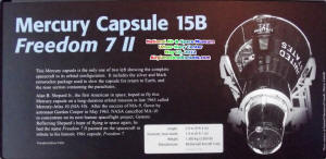
Mercury Capsule 15B - Freedom 7 II Placard
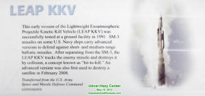
LEAP KKV Rocket

H-1 Rocket Engine
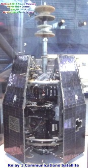
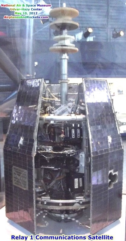
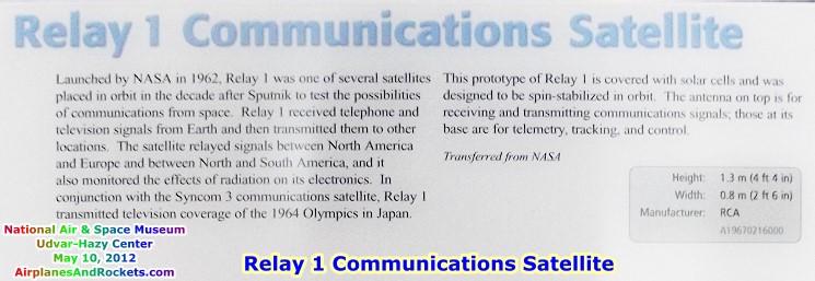
Relay 1 Communications Satellite

Relay 1 Communications Satellite Placard
Manufacturer: RCA Astro Electronics
Country of Origin: United States of America
Dimensions: Overall: 4 ft. 4 in. tall x 2 ft. 6 in. wide (132.1 x 76.2cm)
Materials: Aluminum, copper, plastic, glass
Launched by NASA in 1962, Relay 1 was one of several satellites placed in orbit
in the decade after Sputnik to test the possibilities of communications from space.
Relay 1 received telephone and television signals from ground stations and then
transmitted them to other locations on the Earth's surface. The satellite relayed
signals between North America and Europe and between North and South America, and
it also monitored the effects of radiation on its electronics. In conjunction with
the Syncom 3 communications satellite, Relay 1 transmitted television coverage of
the 1964 Olympics in Japan.
This prototype of Relay 1 is covered with solar cells. The antenna on top is
for receiving and transmitting communications signals; those at its base are for
telemetry, tracking, and control. In orbit, Relay used spin-stabilization to orient
the antennas to communicate with Earth.
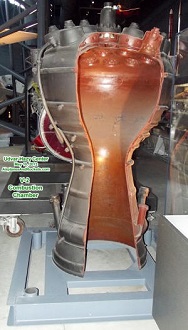
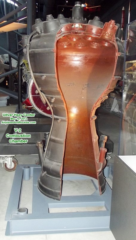
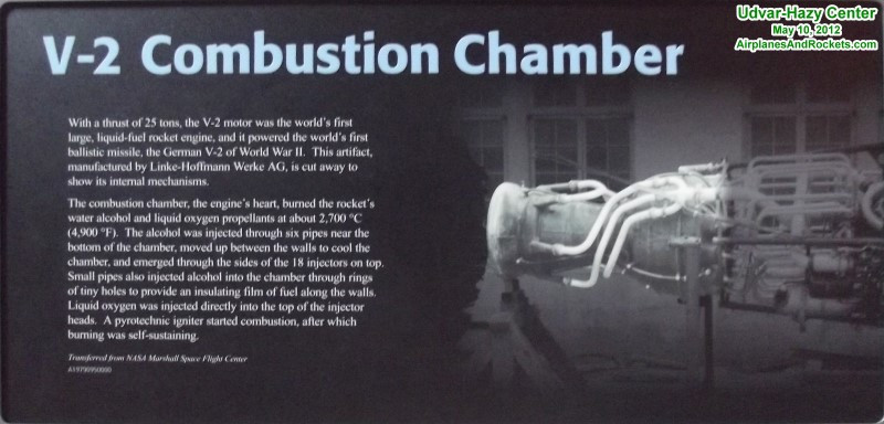
V-2 Rocket Combustion Chamber

V-2 Rocket Combustion Chamber Placard
Manufacturer: Linke-Hofmann
Werke AGCountry of Origin: Germany
Dimensions:
Overall: 6 ft. 5 in. tall x 3 ft. 9 in. wide (195.58 x 114.3cm); diameter, each
injector, 21 in.; diameter, outside, nozzle, 29 in.
Materials:
Steel
With a thrust of 25 metric tons (56,000 lb), the V-2 motor was the world's first
large, liquid-fuel rocket engine and powered the first ballistic missile, the German
V-2 of World War II. The combustion chamber was the engine's heart and burned the
propellants, water alcohol and liquid oxygen, at about 2,700 ºC (4,900 ºF). Water
alcohol was injected through six pipes near the bottom of the chamber, moved up
between the walls in order to cool the chamber, emerging through the sides of the
18 injectors on top. Small pipes also injected alcohol into the chamber through
rings of tiny holes in order to provide a insulating film of fuel along the walls.
Liquid oxygen was injected directly into the top of the injector heads. A pyrotechnic
igniter started combustion, after which burning was self-sustaining.
NASA Marshall Space Flight Center gave this artifact to the Smithsonian in 1975.
|


.jpg)