|
A long time ago (circa 1977) I bought a used
glider winch at an auction held by the Prince Georges Radio Club, in Maryland. It
cost me somewhere around $25, which was a lot for me in the mid 1970s. The motor
and control circuitry was contained in a plywood box, with a jack for the foot switch
and terminals to clamp jumper cable to from a car. In looking at these plans for
the AAM Glider Winch shown here from the April 1973 American Aircraft Modeler, it
looks a lot like mine, only mine was in a wooden in a box. It worked extremely well for my 99"
Windfree and 99"
Aquila sailplanes. Unfortunately,
I sold it shortly after getting married in 1983 (couldn't eat the winch). I would
love to have it back. Actually, what I would rather have at this point is a
winch that is powered by a cordless drill that would be lighter weight and more
compact. I cannot find any commercial models, and not even much in the way of
plans.
AAM Glider Winch
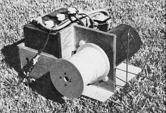
Complete winch. Note position of anchor pins balances the 'pull
of the line during tow. This complete winch weighs only 53 lb.
Lightweight six volt winch for three-pound RC gliders uses turnaround pulley for
convenient pilot operation. Can hoist the big gliders on 12 volts.
By George Steiner
Winches, winches, winches. You see one, you've seen them all. This one pre-sented
here is what I consider a little more refined than the average run-of-the-mill type.
This winch wasn't conceived by one person. I made observa-tions for a long time
at various meets and flying fields and then created what I believe are improvements.
Many people with different ways have approached the idea of shooting a glider into
the air. I have worked with Gerry Wolfram of the South Bay Soaring Society on winching
problems and want to give credit to him and others for their basic ideas.
This winch is ideal for the Sunday fly glider buff-about as light a battery-operated
winch you will be able to find (53 lb.). Most others are well over the 75-lb. range.
It can be constructed in your own hobby workshop, as there is no machine work involved.
If you are a modeler you shouldn't have any trouble with this project by using already
available materials. Basic construction is straightforward and general information
on materials can be taken from the drawing.
Specifications: (1) six volt battery. (2) 12 volt starter motor. (3) Speed (no
load with starter motor modified, remove third field): 3400 rpm. (4) Speed (under
average load, hoisting a three lb. glider): 2000 rpm. (5) Average current on no
load condition: 45 amps. (6) Hoisting line speed under load (average three-lb. glider):
1316 ft./m in. (7) Hoisting glider speed with a two- to three-lb. glider: 18 mph.
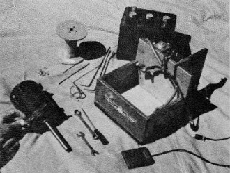
Beginning final assembly of the system. Note the long shaft on
the old starter motor which was resurrected from a junk yard.
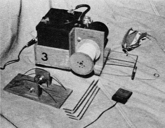
The complete system. Foot switch operated by the pilot. By pulsing
the switch the tow strength can be modulated to suit wind conditions.
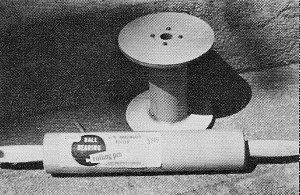
The heart of the lightweight all-wood pulley is a section cut
from an ordinary rolling pin.
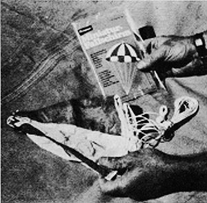
To bring the tow ring down after a release, a model rocket parachute
is ideal.
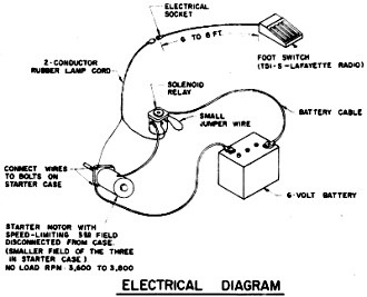
Electrical Diagram
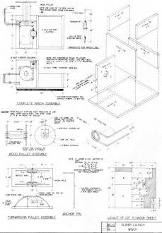
Mechanical Diagram & Assembly
The basic layout of the 1/2" ply-wood is simple enough; decide at this time what
size battery to use. I used a small VW type 6-3/4 x 8-3/4 square, the smallest auto
battery to be found. It works fine but not for contest work. After nearly 35 to
40 hoists into the air it will need to be recharged. If in doubt, make the winch
box the larger size as noted on the drawing; this will allow you to use almost any
larger size battery and fly for several days without recharging. There will also
be enough space to store the anchor pins and foot switch if desired.
After cutting out the basic frame-work, do the detail work on part "E" board
before gluing and nailing it together. It will be much easier to drill the holes
this way. In positioning the starter on "E" you may place the starter in any circular
position desired. The position shown on the drawing will place the starter hot terminal
on top. If you think you will have problems with the cables in such close quarters,
I suggest you rotate it 180 degrees.
After making sure the starter will fit board "E" with the mounting bolts, remove
and continue with the whole assembly, making sure not to use nails that are too
large, as they will split the wood. Use a small finish nail such as No. 16 gauge
1-1/4 to 1-1/2" long.
A couple of coats of urethane varnish on all woodwork is a good idea. It helps
cut down on the splinters and gives a finished product look to your winch.
The wood pulley assembly is made up of a household rolling pin and a 6 x 12"
piece of 1/4" birch plywood.
The end plates were rough cut on a jigsaw. Drill a 5/8" hole in the middle. Take
a short piece of 5/8" dowel about eight in. long and place the two end plates through
the holes. To true up the end plates, place the 5/8" dowel in a small vise near
a bench grinder. Position the vise so the two end plates can be rotated against
the grinding wheel. After several rotations around the 5/8" dowel and against the
grinder, you will have very true rotating end plates.
The rolling pin from the hardware store will have to be disassembled by knocking
off the handle at one end. Remove the steel shaft and keep for one of the anchor
pins. Make sure the hole through the rolling pin is 5/8". Of the three kinds I had,
the best one was made by EKCO Housewares of Franklin Park, Illinois. Cut to size
using a power bench saw. Do not try to cut it by hand because it is almost impossible
to get a square surface. You want as little wob-ble in the end plates as possible.
Out of round and poor balance of this pulley will hinder your winch rpm as much
as 50%.
Use the 5/8" dowel as a jig to center the end plates on the rolling pin while
you epoxy and screw in place. This will assure more accurate alignment to give a
better and more true pulley.
Drill a 1/4" hole 1-1/4" in from the side for your 1/4" dowel shear pin. This
shear pin is a good safety feature in case the pulley becomes locked up. Only once
did it break for me, and I was pleased that it did. If a steel pin is used it will
more than likely split the wooden rolling pin in half and cause other dam-age to
be sure.
The remote pulley (otherwise known as the turnaround pulley) is made from a Schwinn
bicycle front hub. It is ideal for this kind of application because it is so easy
to mount. Having ball bearings and the sturdiness of its construction makes it perfect
for this application. One shouldn't have any problem assem-bling this unit off the
drawing. Be sure to epoxy the large 3/16" wire loops in place. Don't forget to cut
the slots out for the hub axle in F2 and F3 before you glue the nail to Fl. This
will make a better fitting job.
The wire guides over the bicycle hub are necessary to keep the line from be-coming
tangled when some gliders veer off to left or right extremes under tow. The line
falling back to earth will some-times end up behind the turnaround pulley. When
retrieving the line, it could get caught in the assembly if it didn't have some
sort of protection to keep the line out of the bicycle hub. If the line gets hung
up in the axle, you are not going to get altitude on the next flight-that's for
sure. If the line pulls hard back to the winch after a launch, check the turnaround
for some kind of line entanglement-it could be hung up on the anchor pins.
The winch line guide is made of spring steel wire from your local hobby store.
To get it formed, I used a one-in. socket gripped into a vise. Start somewhere in
the middle and start twisting. A suggestion is to practice with a piece of soft
wire like a coat hanger. This should give you some practice in the technique to
be used for the hard-to-bend spring steel wire. Cut off the excess to give the seven-in.
length to fit into board "E" brass tubing. Do not epoxy the guide in place because
it will be unhandy in transporting. Keep it so it can be removed after a day's flying.
Remember the notation "Caution" on the drawing. Cut off the excess to give the seven-in.
length to fit into board "E" brass tubing. Do not epoxy the guide in place because
it will be unhandy in transporting. Keep it so it can be removed after a day's flying.
Remember the notation "Caution" on the drawing.
The secret to using a light wood pulley is the use of this winch line guide.
If the guide is forgotten, the pulley will shatter on your first tow. The advantage
of using a light wood pulley virtually eliminates any flywheeling action. A heavy
pulley will cause nothing but trouble. The backlash will be so bad you will spend
hours un-tangling the winch line after each tow. Keeping the pulley light is the
key to eliminating backlash action. A heavy pulley will cause nothing but trouble.
The backlash will be so bad you will spend hours untangling the winch line after
each tow. Keeping the pulley light is the key to eliminating backlash problems.
The starter motor is a Ford 12 V 1954 to '64 long shaft vintage. The wrecking
yard is a good place to start looking for one. Be sure the bearings are good and
the armature isn't dragging the fields.
A modification to the starter should be made in order to increase its efficiency
by removal of the third small speed-limiting field. This is done by cutting one
of the lead wires to it. It is easy
to recognize which one. Observe the third field winding in the starter re-moving
the electrical connection on the smaller field of the three. I found that this modification
increased the rpm by 33% and lowered the current drain by 15%. The no load rpm should
be checked on six volts. If you cannot get over 3400 rpm, something is binding or
out of balance and should be corrected. This is important because when hoisting
the three- to four-lb. or more gliders you need all the power you can get. A handy
instrument in checking the rpm is the Heathkit Thumb Tach. This can be done by placing
a piece of black tape across one end of the wood pulley as a light source interrupter.
The starter solenoid can be picked up at a local auto parts store. Be sure it
is a six volt unit, otherwise intermittent operation will result.
At least at one time, the AMA Plans Service offered a full-size plans of the
AAM Glider Winch and other models at a very reasonable cost. They will scale the
plans any size for you. Try out my
Scale Calculator
for Model Airplane Plans.
https://www.modelaircraft.org/plans.aspx
|