|
Walter Musciano is a very familiar name to modelers who cut
their teeth on on control line model airplanes back in the middle
of the last century. His flying hobby began in the 1930s are a Brooklyn,
New York, schoolboy. He won his first contest in 1936. Since that
time, Mr. Musciano has designed scores of model airplanes and won
numerous contests. This article from the July 1951 edition of
Air Trails covers the building of his famous
 Stunt
Rocket. It was a breakthrough design due to its large size and huge,
powerful ignition engine. AMA Plans Service still sells the plans. Stunt
Rocket. It was a breakthrough design due to its large size and huge,
powerful ignition engine. AMA Plans Service still sells the plans.
Many books by Walter A. Musciano are available through
Amazon.com.
Stunt Rocket Article & Plans
By Walter Musciano
|
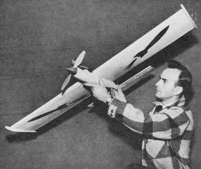
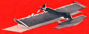
Designer Musciano with his giant; upright ignition motor
was early experiment.
|
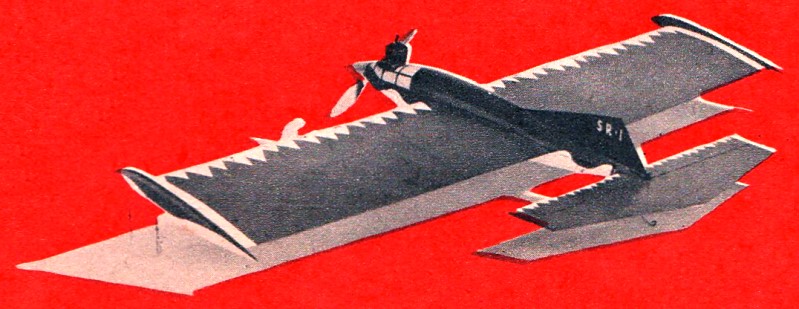
The Stunt Rocket is an outstanding example of the application of
modern styling to a proven force arrangement for competition stunt
models. Its large size (550 square inches) is a departure from "mosquito"
stunt models.
Instead of attempting realism by means of a bubble canopy (a
la military motif) or open cockpit (pre-war private plane type),
we omitted these creators of parasite drag and painted a flush cockpit
in the nose section similar to the more recent full-scale rocket
research planes. The projectile fuselage profile coupled with the
Froom needle nose spinner completes the illusion of a supersonic
rocket plane with the assistance of the rakish fin.
In view of the fact that the wing is the main structure, it is
first on the list to be fabricated. Only the tip and root rib patterns
have been given on the plan. These should be cut from the specified
stock; then cut rectangles to the rough dimensions of the remaining
ribs. Spot-cement these, rectangles to each other with the root
and tip ribs at either end. Now carve the ribs to shape using the
tip and root ribs as patterns.
It will be noted that the leading portions of all ribs up to
the front spar are identical. Notch the ribs for spars, leading
edge and sheet covering. The forward bottom spar is pinned to the
workbench directly over a full-size plan and the ribs cemented to
it. This bottom spar must be raised from the workbench 1/16" with
slivers of balsa before the ribs are attached. Cement the top spar
in place and add the leading edge. Add the rear top spar and top
trailing edge piece; do not twist wing structure during this operation.
When dry remove the structure from the workbench, bevel top trailing
edge piece as indicated, and cement the remaining spar and trailing
edge piece in place.
The bellcrank assembly is installed. Select a commercial type
with proportions similar to the one illustrated and bolt it to a
piece of hardwood which is cemented securely to the wing structure.
Attach a length of 1/16" music wire to the bellcrank to serve as
control rod. Pass the lead-out lines through the holes in the ribs
and attach securely to the bellcrank.
The 1/16" sheet webs between the ribs along the spars are cemented
in place. Grain should run vertically on these webs and they should
be cemented to ribs as well as spars. Note that no web is required
at bellcrank installation. Wing leading edge is covered with 1/16"
sheet balsa forward of front spars. We prefer, a slow-drying cement
for this operation. The wing center section is also treated in this
manner.
|
Something in the way of a stunt model, you say? Something
big? Here's a project to keep you busy at the bench for
awhile, then provide lots of flying fun.
|
Sandpaper the entire structure well and re-cement all joints,
Cover wing with heavy paper, using cement as the adhesive. Before
watering the wing cut end plates and carve and sand to a streamline
shape.
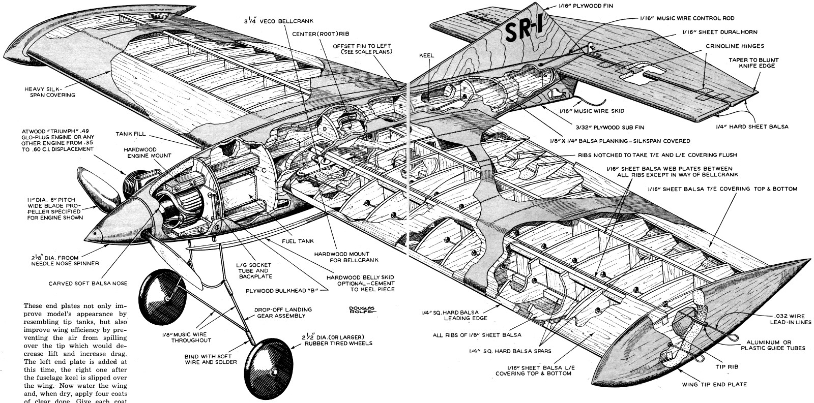
These end plates not only improve model's appearance by resembling
tip tanks, but also improve wing efficiency by preventing the air
from spilling over the tip which would decrease lift and increase
drag. The left end plate is added at this time, the right one after
the fuselage keel is slipped over the wing. Now water the wing and,
when dry, apply four coats of clear dope. Give each coat plenty
of time to dry.
Fuselage is built directly onto wing. Cut the 1/4" sheet balsa
keel, being sure to notch it for engine mounts, fuel tank, wing
and stabilizer. Slip in place, cement keel to wing. While this is
drying cut all formers from specified stock and cement them to keel.
Cement engine mounts securely to keel; this location will vary according
to the engine you intend to use. Plan the mount placement carefully
before notching bulkhead "C."
We used a drop-off type of landing gear with success. If you
prefer a fixed gear the performance should not suffer too greatly.
Make the take-off gear first. Be sure to bind joints well with soft
wire and solder liberally. Use largest wheels you have on hand (over
2 1/2" dia.) because they are less likely to snag in grass or other
undesirable surfaces.
Cut a piece from a discarded tin can to the shape shown on plans.
Now slip the brass tubing over take-off gear prongs and lay this
on tin backplate. Solder the tubing, with prongs still inside to
backplate. Use plenty of flux and solder well. When cool, the prongs
can be removed and now you will be certain that they fit tubes exactly.
Backplate assembly is screwed or bolted to the bulkhead "B."
Install fuel tank. Attach Neoprene or plastic tubing to the tank
vents. Any commercial stunt tank will perform well if it is correct
size for the engine. Cut tail surfaces to shape and sand to streamline
section. Hinge elevator to stabilizer, using crinoline strips, and
fasten securely the control horn to elevator. The stabilizer is
cemented to keel and the control rod connected to horn. Test the
control system and apply three coats of cleat dope to tail surfaces.
Planking the fuselage is much easier than some modelers would
have you believe. Using a slow drying cement, attach each successive
strip 180 degrees apart. In this way fuselage will ·not bend out
of shape during construction. Sides of the planking strips must
be beveled and all strips should taper uniformly towards the tail.
Sand fuselage well when dry.
Bolt engine in place and add the Froom aluminum spinner to it.
Now select soft balsa blocks for nose pieces. These are cemented
lightly along horizontal center line and carved roughly to shape.
Separate the blocks, and hollow them around the engine.
Cement the blocks to plywood bulkhead "B" and to each other, again
very lightly, and this time carefully carve blocks to fair smoothly
between fuselage and spinner. Sand smoothly, then remove and hollow
as plans indicate. Fuel-proof the cowl interior and replace nose
.pieces, this time permanently.
Fin is cut from plywood sheet and sanded smooth, Cut a recess
in fuselage top and cement fin securely in place. We covered the
fuselage, a small area at a time. After this operation, three coats
of clear dope were applied with light sandings between each coat.
The prototype model is colored red and white with a gray cockpit
enclosure. Apply three coats of white dope and mask-off, then add
red dope.
Be sure to use fresh tape at all times and push edges close to
model's surface with your fingers to prevent color from seeping
through. The white leading edge trim, rocket insignia and all lettering
were made from Trim-Film. Two coats of transparent fuel proofer
should be applied to entire model.
In view of the fact that model was flown without any landing
gear, we operated over a grassy site and in this way the belly of
model did not get scratched during landing. Take-offs were not hampered
by the grass because of forward location of gear and large size
of wheels:
If a fixed gear is used we recommend as smooth a flying site
as possible. Our initial flight was conducted with 0.016" diameter
lines, 60 feet in length. Once we were familiar with the flight
characteristics (extremely maneuverable with moderately high speed
- 70 mph) , we graduated to seventy and then eighty foot length
of 0.016" stainless steel flight lines. It is with these longer
lines that the model really does its stuff!
We experienced no difficulty in keeping lines taut with the fin
offset shown. However, should the model indicate a tendency to turn
toward the circle center, a one or two degree engine offset should
remedy this condition. If balanced as shown and built carefully
and flown with good sense, the Stunt Rocket will provide many flights
that are truly "out of this world."
Bill of Materials
Fuselage. 1. pc. 1/4" x 2" x 36" hard balsa, keel. 1 pc. 1/8"
x 2" x 18" medium balsa, formers. 1 pc, 3/16" x 3" x 3" plywood,
bulkhead "B". 20 pcs. 1/8" X 1/4" x 24" medium soft balsa, planking.
2 pcs. 3/8" x 1/2" x 6 1/4" hardwood, engine mounts. 2 pcs, 1/8"
I.D. x 1 1/2" brass tube, L.G. sockets. 2 pcs. 3 1/4"· x 3 1/4"
x 1 1/4" soft balsa, nose blocks. 2 2 1/2" dia. or larger rubber-tired
wheels. 1 pc. 1/8" dia. x 36" music wire, take-off gear. 1 sheet
Silkspan; covering.
Wing. 7 pcs. 1/4" X 1/4" x 36" hard balsa, spars, leading edge.
6 pcs. 1/8" x 3" x 36"

Stunt Rocket
Skeleton Sketch
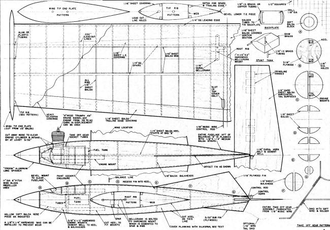
Stunt Rocket
Plans
Notice:
The AMA Plans Service offers a
full-size version of many of the plans show here at a very reasonable cost. They
will scale the plans any size for you. It is always best to buy printed plans because
my scanner versions often have distortions that can cause parts to fit poorly. Purchasing
plans also help to support the operation of the
Academy of Model Aeronautics - the #1
advocate for model aviation throughout the world. If the AMA no longer has this
plan on file, I will be glad to send you my higher resolution version.
Try my Scale Calculator for
Model Airplane Plans.
Posted January 31, 2015
|