|
From what I can remember, this
October 1972 edition of American Aircraft Modeler magazine is the first
I received after joining the Academy of Model Aeronautics (AMA). I was thrilled
to be having a monthly modeling magazine delivered to my rural home because it was
rare that a copy of Flying Models or Model Airplane News would appear on the rack
in our local convenience store. Unlike today's age of instant and ubiquitous information,
getting ahold of desired reading material was not nearly as easy before the Internet.
Somehow, I managed to retain possession of that issue for nearly 40 years now. With
few exceptions, everything else from my childhood has vanished.
I remember being particularly interested in the Charybdis because it satisfied
the desire for a lot of different modeling interests - helicopters, airplanes, and
nitro-powered engines. In 1972 I was 14 years old and didn't have a lot of walking
around money - only what I scraped as profit from my paper delivery route and odd
lawn mowing jobs. So, I never actually built one, but I sure did pour over the plans
and article intently.
Having forgotten about the Charybdis until running across it again, I'm thinking
maybe a modern, electric-powered version would make for a great winter project.
Check back here in the spring to see if I make good on my idea.
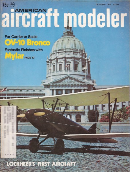
Charybdis
With a twist of your wrist, this single-bladed, .010-powered thing swishes aloft.
Great fun and easy to make.By H.D.M. Sherrerd, Jr.
 In Greek mythology, Charybdis was an extremely
powerful whirlpool off the Sicilian coast. This helicopter is not particularly powerful,
but like its namesake, everything revolves at a rather high rate of speed, and to
that degree at least the name was appropriately chosen by the inventor, Charles
W. McCutchen of Princeton, New Jersey. In Greek mythology, Charybdis was an extremely
powerful whirlpool off the Sicilian coast. This helicopter is not particularly powerful,
but like its namesake, everything revolves at a rather high rate of speed, and to
that degree at least the name was appropriately chosen by the inventor, Charles
W. McCutchen of Princeton, New Jersey.
Charybdis was developed 18 years ago, while McCutchen was living in Cambridge,
England, and caused something of a sensation when he took it to the British Nationals
of 1954. Since that time, variations on the "McCutchen Machine," as the design is
more generally called, have occasionally appeared in European magazines, but a prophet
is usually without honor in his own country, and the Charybdis seems to have been
completely ignored in the U.S.-a pity, since it is no tougher to build than a good
hand-launched glider, and more fun than tying firecrackers to your old flying scales.
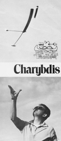
Construction
Construction is quite simple, with the emphasis on strength. The blade and stabilizer
are of sheet rather than built-up, the motor and balance arms are of spruce, and
the hub is reinforced with 1/16th plywood. The motor arm is inlaid into the lower
surface of the blade, the reinforcing plate double-glued over the joint, and the
whole bound with silk or other light cloth. This area is then virtually unbreakable,
and also a good flat surface for the balance arm to bear against. You can, of course,
glue or even bolt the balance arm in place, but Charybdis is much easier to carry
around if the arm is detachable.
The blade is simply a 2' x 2" lath of 1/4-in. medium sheet balsa, shaped to a
constant Clark Y section. No wash-in, no wash-out, no dihedral breaks; the squarest,
easiest wing you ever made. Use a template to maintain section accuracy. Don't try
something with undercamber instead. McCutchen tried both undercambered and curved-sheet
airfoils, and found the resulting Charybdis to be unimproved, at best, or just plain
unstable, at worst.
The stabilizer struts are 1/8th hard sheet sanded to a streamline section. Use
plenty of glue and perhaps even some silk reinforcing at the strut-to-stabilizer
joint, the only vulnerable area of Charybdis. The stabilizer itself is also 1/8th
hard sheet, but is given a lifting section. Be careful to set it at an angle of
at least -50 or -60 relative to the blade, as this is most important.
The motor pod is so designed mainly because it looks good. The streamlining probably
helps a bit, but is really unnecessary. On the other hand, it does provide a solid
mass behind the firewall (if you can call it that) and a little more weight. (The
Cox 010 is awfully light.) The 1/8-in. plywood firewall is inlaid into the motor
arm, and the pod itself built up from the same 1/4-in. stock used for the blade,
or anything else in the scrap box, then carved and sanded to shape With the motor
inverted, as shown in the photos, the mounting screws bear through into the spruce
arm instead of the soft balsa. Add a wire guard loop if you think it necessary,
but the prop generally seems to be enough protection for the glow plug even when
landing on bare spots.
This has got to be the easiest helicopter type thing yet-only
one rotor blade!
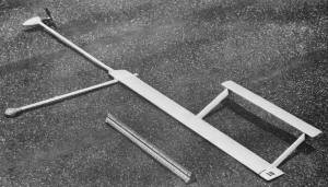
Rubber band mounted weight boom affords easy adjustment of CG
and crash protection.
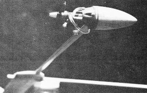
Inverted Cox .010 works much better than if it were upright,
but no one knows why. Don't fly over concrete.
Thinned, clear, hot, fuel proof dope is used on everything except the motor pod
and adjacent portion of the motor arm, where straight dope is used for extra protection.
Colored dope could be used, of course, and should produce a pretty jazzy effect
with Charybdis revolving at the speed it does.
The inverted position of the Cox 010 has been found the best after much painful
trial and error. The tank outlet is slightly high, but the fuel line itself is at
the extreme outside of the swept circle, and fuel does not have to fight centrifugal
force on its way to the needle valve. The other arrangements that seem so obvious
either don't work for one reason or another, or offer no particular advantage.
Because of variations in engines, fuels, weather, altitude, etc., finding the
proper needle valve setting is something you must do yourself; there is nothing
else for it. But there is one peculiarity of the system worth mentioning that makes
all the difference in running time: an odd combination of forces and pressures is
at work that requires blocking off one of the filler nipples for maximum engine
duration. With both nipples open, engine run will be 15 to 20 seconds. With one
blocked off, the run will be well over a minute. This can be done with a short length
of pinched-off tubing, or a longer piece running to the pressure-tap nipple. With
this latter system you don't lose the short piece in the grass while fueling-it
stays attached to the pressure-tap. You can, of course, use a control-line tank
and find the optimum setup yourself. However, the shortest fuel line is always the
best, and use of the integral tank has the advantages of simplicity, strength, and
aerodynamic cleanliness.
Flying
Launching may seem a bit hairy at first, but is really no problem if the CG is
located approximately as shown. To avoid losing fuel from the inverted tank, turn
the Charybdis upside-down and start as usual. Now grasp the hub area with your fingertips
on the blade leading edge and thumb on trailing. Raise the whole affair over your
head while simultaneously turning it upright; snap your wrist to start rotation,
and push upwards. Then duck, and run into the wind, since you probably haven't got
the carburetion right to begin with. Try again, until the engine continues to run
and Charybdis climbs away like a startled mallard.
An alternate launch method is to gusset the general area of the CG, drill a small
hole at the approximate center of rotation, and impale the Charybdis on a headless
nail driven into the end of a stick. In this case Charybdis will simply fly itself
off once it picks up sufficient speed. McCutchen remarks that this is a good idea
while getting the carburetion and balance unscrambled, since it prevents powered
crashes while in an unstable condition.
Once properly trimmed, Charybdis is remarkably stable. The rate of climb can
be varied by adding or removing clay, and by sliding the balance arm in and out.
But this will not make as much difference as you might think, and unless carried
to extremes, will not seriously disturb autorotation characteristics following engine
shut-down. If the Charybdis is really out of balance, of course it won't take off
to begin with. Changing the stabilizer angle, on the other hand, will make a great
difference in rate of climb. An adjustable stabilizer, or at least a movable tab
on the' fixed one, would permit complete freedom of experimentation.
The other factor that most strongly affects performance is power. With the 3
x 1.25 standard .010 prop, time from launch to touchdown averages around a minute
and 30 to 45 seconds. Charybdis climbs steadily for several hundred feet, depending
on engine run, then descends in autorotation for anything from 30 seconds to a minute.
On one memorable flight of this sort, the Charybdis got hung up in a thermal at
100 feet or so and just sat there, silently autorotating over one spot for something
close to two minutes. Total time was 3:15 for a rather different max flight.
But to really have a ball with Charybdis, try this: Turn the prop around to reduce
thrust, or use a 4-1/2 x 2, .020 prop, pile more clay on the balance arm, maybe
try a masking tape trim tab on the elevator-anything to hold it down. It will take
a while to work out, but you can get the Charybdis to hover waist-high. It will
first sink to a grass-cutting level, then find an equilibrium altitude in ground
effect at two or three feet, and just sit there, drifting with the breeze, following
the contour of the ground. McCutchen rigged one to do this so well that it would
go down the gentle bank of a stream, cross over, then climb the opposite bank and
continue wandering off across the fields. He says it was quite upsetting to casual
observers along the flight path.
While hovering like this, Charybdis will produce the weirdest sound you have
ever heard outside a science-fiction movie. You'll think the Martians are coming-it
is a kind of whoop-whoop-whoop-whoop gradually increasing in pitch and frequency,
with an underlying humming note, and the scream of the engine. All this may be only
a peculiarity of the author's Charybdis, and may not be true for others-even working
from the same plans, everyone builds slightly differently. But for the Charybdis
in the photos it's real. And strange.
AAR Note: The Charybdis' principle of flight is very similar to that of the familiar
maple tree seed. Here is
NASA's
page on them.
<click for larger version>
Notice:
The AMA Plans Service offers a
full-size version of many of the plans show here at a very reasonable cost. They
will scale the plans any size for you. It is always best to buy printed plans because
my scanner versions often have distortions that can cause parts to fit poorly. Purchasing
plans also help to support the operation of the
Academy of Model Aeronautics - the #1
advocate for model aviation throughout the world. If the AMA no longer has this
plan on file, I will be glad to send you my higher resolution version.
Try my Scale Calculator for
Model Airplane Plans.
Posted October 31, 2010
|