|
Website visitor Richard P. wrote
to ask for me to scan articles from the June 1971 edition of American Aircraft Modeler.
The two articles, subtitled "A Study in Design Ideas," feature two control line stunters,
the F-4 Phantom and the B8 Crusader, presented together as complimentary models but with
varied construction techniques. Designed and built by two separate modelers, Bill Suarez
and Vic Macaluso, respectively, they are similar in that both represented at the time
"the Navy's best current jet fighters," both have tricycle landing gear, have wingspans
in the 55-60" range, and use inverted mounting for a .35-size engine. The big difference
between the two is that the Phantom ahs a built-up wing while the Crusader has a foam
core wing. The Crusader uses anhedral in the wing - uncommon for a stunter.
See the accompanying Phantom
article.
A Study in Design Ideas
Two consistent contest-winners, these semi-scale stunters are based on the Navy's
best current jet fighters. Should be most effective at the Nats. Crusader
 By Vic Macaluso By Vic MacalusoPhotos by Bill Boss
Why the Crusader? Stunt has come a long way since
the Barnstormer and Profile Mustang, and today's trend is toward larger, more realistic
aircraft. Seeing all the semi-scale stunt ships at the 1969 and 1970 Nats convinced me
that scale-like planes are going to be around for quite some time. For that reason, I've
switched from the Classic stunt ships, such as the Nobler, Smoothie, etc., to designs
like the Crusader.
The Crusader was chosen because of its unique look, high wing, ventral fins, Sidewinder
missiles and drop tanks - all things the ordinary stunt flier would not consider. Something
completely different was what I wanted, but could it be made to fly? If a low wing with
dihedral could be flown successfully, why wouldn't it also work upside down? Thus the
Crusader was born.
The plane's construction is kept fairly simple through the extensive use of hollowed
balsa blocks and box-type construction of the fuselage, balsa sheet for the tail surfaces
and flaps, and a slightly modified foam wing. By paying particular attention to the selection
of light wood and hollowing out the blocks as much as possible, the plane's weight should
be 50 to 52 oz., about right for a good 35 engine.
Construction
Epoxy was used for laminating the nose section and for installing the motor mounts
and wing; white glue was used for most of the other construction. However, the choice
of glue or epoxy is up to the individual.
Fuselage: Cut the fuselage sides from 1/8" sheet balsa and the doublers from 1/16"
plywood. Glue the doublers to the fuselage sides. Next, cut 1/2 x 3/8" hardwood engine
mounts to the proper length and cement them to the fuselage sides where indicated. Engine
mount location must be exact because the thrust line with the anhedral wing can be critical.
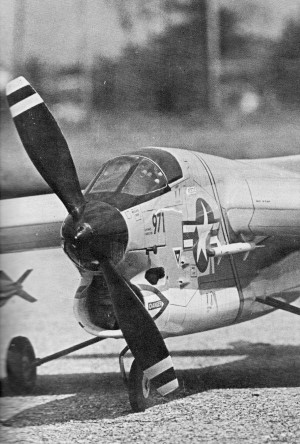
It is the fine detailing that makes this model look like the Crusader. Takes patience.
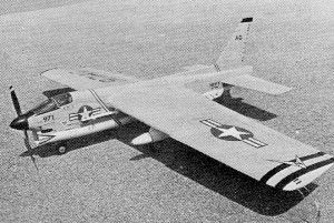
Rear view shows wing's anhedral, unusual ventral fins, drop tanks and rockets.
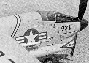
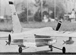
More of that beautiful detailing. This is a much-flown model kept clean and waxed.
While the fuselage sides are setting up, cut out formers F-1 through F-5. Draw a vertical
centerline on all formers and a straight line on the work table. These markings will
aid in aligning the fuselage during assembly. Cement F-1 and F-2 in place. Using their
centerlines, line up the formers on the table and align the fuselage. Hold in place until
set.
Glue in the remaining formers and again use the lines on table to align the fuselage
structure. Hold in place while the assembly dries. When completely set, drill engine
mounting holes (for a Fox 35) and install blind nuts to the top of the engine mounts.
Install the engine, extension shaft, and spinner.
Next, build up the top, bottom and tail of the fuselage by tack gluing a 1 x 2 1/2
x 36" block to the fuselage top. Permanently glue a d 1 x 2 1/2 x 20" block on top of
the 36" block at the nose end to provide sufficient thickness for the cockpit area.
The fuselage bottom is formed from a 1 x 2 1/2 x 36" plank cut as shown at former
F-3. Tack glue the bottom blocks in place. Using the plans as a guide, shape the fuselage
as shown in the top and side views. Pay particular attentions to the contour in the cockpit
area, which will be used later as a mold for making the canopy. When all carving and
shaping is done, pop off top, bottom and tail blocks and hollow out as indicated by the
dotted lines. Hollow as much as possible for the lightest structure.
The landing gear is made up next and installed. Attach the nose gear to former F-1
with J bolts. Mount the main gear on a 1/8" plywood plate and install it in the fuselage.
Wing: The wing was made from a Chipmunk wing (Foam-Flight Wings, 628 W. St., Mankato,
Minn.). Start construction by sanding the anhedral angle in the root of each panel. To
achieve the proper angle, place the root of each panel each edge of a straight table
or work bench and block, up the other end of the panel (before wooden wing tip is installed)
1 3/4" off the table. Holding a coarse sanding block exactly vertically, sand across
the wing root until the proper angle is obtained.
Before the wing sections are assembled, install the 3" bellcrank and leadouts in the
correct inboard panel. For mounting the bellcrank any of the several methods suggested
on the instruction sheet with the wing kit may be used. After the bellcrank and leadouts
are installed, assemble the wing. Using the foam packing blocks as a jig, set up the
wing halves so that the center joint is aligned perfectly. Remove the wing halves from
the jig, and let cure overnight. The center joint then is wrapped with fiberglass tape
and epoxy and again left to cure overnight.
At this point, add the wing tip blocks which are made by tack gluing two 1 x 3 x 10"
soft balsa blocks together. Tack glue the assembly to the wing and carve the tips to
shape. Next, remove and hollow out the carved tips. Add a 3/4-oz. weight to the outboard
tip and mount both tips permanently. Make flaps from 1/4" balsa sheet, add hinges and
control horns and install on the wing.
Tail
Surfaces: Butt join as many pieces of 1/4" sheet balsa as needed for the fin and rudder
and cut them out. Sand in the airfoil shape. Cut out the rudder and re-glue it with the
offset shown on the plan. The stabilizer and elevators are made from 3/8 x 3" sheet.
Cut all the pieces to shape and tack glue them together. Using a sanding block, sand
a taper from 3/8" at stabilizer root to 3/16" at the stabilizer and elevator tips. Next,
sand in the airfoil shape shown on the plans. When all shaping is done, separate the
elevator from the stabilizer and round off the elevator-stabilizer joint. Add the control
horn and hinges to complete the assembly.
Final Assembly: Use epoxy to attach the wing in the fuselage cutout already provided.
The wing must be square to the fuselage. While this is curing, bend the elevator pushrod
to shape from 3/32" dia. music wire.
When the wing is permanently affixed to the fuselage, make the appropriate cutout
in the fuselage to accept the stabilizer-elevator assembly (cut former F-5 at dotted
lines). Attach the pushrod to the flap and control horns. Slide the stabilizer back and
forth to get a zero-zero indication on flaps and elevator, Then glue in place. The remainder
of the fuselage cutout is filled in. Replace part of former F-5 and cement the tail block
in place.
Hollow out the engine cowling and cut in all necessary holes. Add cowl fasteners of
your choice.
I used a jack for engine starting, since it provides a neat appearance, is convenient,
and requires fewer holes in the cowling. The jack installation can be eliminated if desired.
Top and bottom fuselage blocks, as well as the rudder-fin assembly and ventral fins,
are permanently glued in place. The model is now ready for the final sanding.
Cock pit Canopy: Carefully draw the outline of the cockpit canopy on the nose section
and cut along those lines. Remove the canopy area in one piece so that it can serve as
the mold for forming a Plexiglas canopy. Heat a piece of 1/16" Plexiglas in an oven and,
when pliable, draw it over the mold. Cut away excess Plexiglas and fit the canopy to
the model. Before installing the canopy permanently, add cockpit detail. For a free ready-made
canopy, send me a photo of the Crusader in its final construction stages. Write: 384
Central Islip Blvd., Ronkonkoma, N.Y. 11779.
Finish: AeroGloss paints and plenty of rubbing were used to finish the plane. Details
for color and markings came from Profile Publication No. 90. Chance Vought F8A-E Crusader.
Lettering detail was done with Instatype dry transfer lettering.
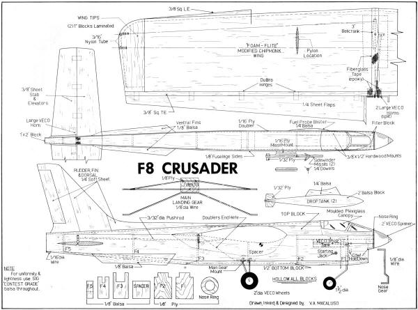 Crusader Plans<click for larger version>
Notice:
The AMA Plans Service offers a
full-size version of many of the plans show here at a very reasonable cost. They
will scale the plans any size for you. It is always best to buy printed plans because
my scanner versions often have distortions that can cause parts to fit poorly. Purchasing
plans also help to support the operation of the
Academy of Model Aeronautics - the #1
advocate for model aviation throughout the world. If the AMA no longer has this
plan on file, I will be glad to send you my higher resolution version.
Try my Scale Calculator for
Model Airplane Plans.
Posted February 22, 2012
|