|
Here
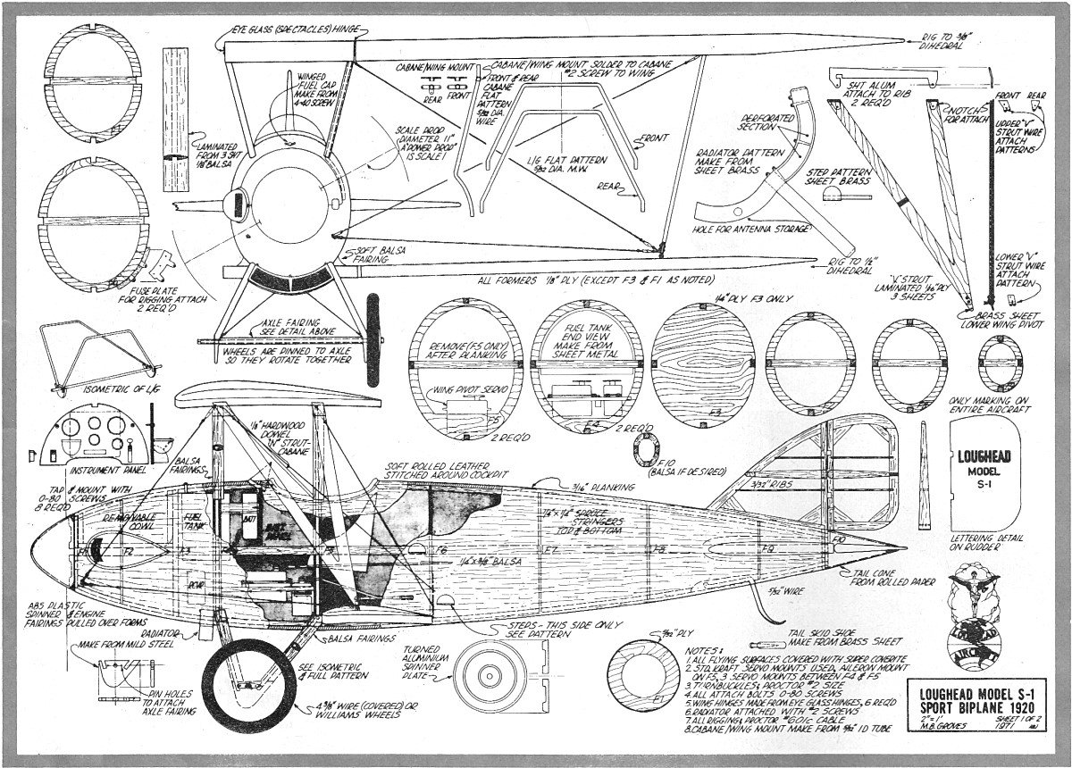
are article and plans for the Loughead Sport Biplane Model S-1 Plans,
that I electronically scanned from page 42 of my purchased copy
of the October 1972 edition of AAM. You might be able to scale up
the image below if suitable plans cannot be located. Plans for this
fine model were drawn by Mr. M. B. Groves. All copyrights (if any)
are hereby acknowledged. Click here for the accompanying
historical article on the
Loughead S-1. "In 1919, Loughead [later renamed Lockheed]
Aircraft entered the small aircraft market with the revolutionary
single-seat S-1 Sport Biplane. Intended to be "the poor man's airplane",
it featured an innovative molded plywood monocoque fuselage for
which the Lougheads, Northrop and Tony Stadlman received a patent.
Its foldable wings allowed the plane to be stored in a garage, and
the lower wings could be rotated to act as ailerons and airbrakes.
Because no suitable engines were available, the company designed
and built its own 25-horsepower water-cooled engine for the S-1.
The S-1 was tested successfully at Redwood City, CA in 1919
by Gilbert Budwig and flew well. After the S-1 completed its test
flights, the pilot said it was the most flyable plane he had ever
flown. The plane went on to make hundreds of flights and proved
to be a very successful design. At an aircraft show in San
Francisco, thousands admired the little S-1 aircraft, but not a
single person ordered the $2,500 plane. Only then did Allan Loughead
realize that the government's sale of war surplus aircraft for as
little as $300 had killed the market for new aircraft. As a result,
Loughead Aircraft closed its doors in 1920 and its assets were liquidated
in 1921. -
Wikipedia"
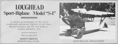 Loughead
Sport-Biplane Model "S-1" Loughead
Sport-Biplane Model "S-1"
A replica-in-miniature of the most technically advanced biplane
of all time.Model includes all the real plane's unique features,
too. Plane on the cover. by Monte Groves, Sunnyvale,
Calif.
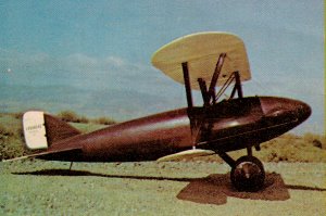
Loughead S1 - Finished side view

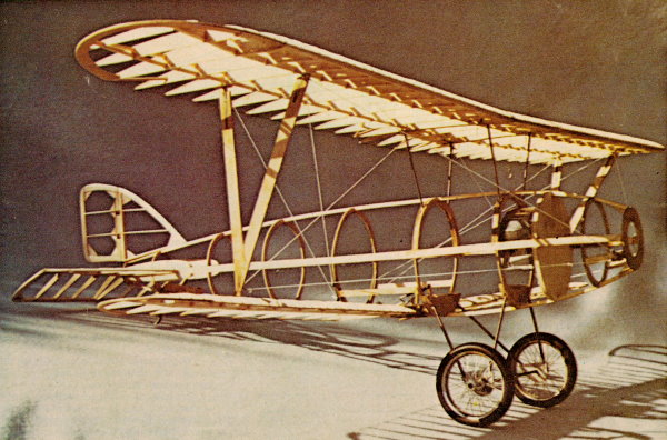
Loughead S1 - Open framework
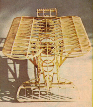
Loughead S1 - Open framework, wings folded
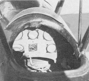
Loughead S1 - That's all the instrumentation the real plane
had, too, but arrangement of dials is only a guess.
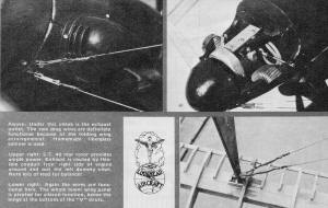
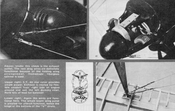
Loughead S1 - Scale detail
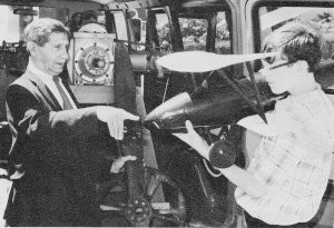
Loughead S1 - The one-and-only Loughead S-1 engine and the one-and-only
Tony Stadlman meet again in San Francisco. As Loughead's factory
superintendent, Tony's support in this research project has
exceeded all bounds.
One can become addicted to early aviation research. After researching
and building a model of Wiley Post's beautiful Winnie Mae (August
1970 AAM), we became interested in the aircraft im-mediately preceding
the Lockheed Vega. Precursor to the Vega was the Loughead Sport-1
biplane, and research into this little-known one-of-a-kind air-craft
has been an engrossing and fas-cinating project. Though built
and flown 52 years ago, with the exception of Allan and Malcolm
Lockheed, most of the original participants are still with us. And
with-out their cooperation, the S-1 project would never have gotten
off the ground. During the Vega research we came across
six photos of the slender little bipe. With these and five or so
others we located in the Lockheed-Burbank files, we began the project.
After two years of constant correspondence and probing into various
personal and public ar-chives, some 55 construction and flying photos
have been amassed. The original 1920 Loughead sales brochure, as
modi-fied, provided all the dimensions. Interviews and correspondence
with Jack Northrop, the principal engineer, Tony Stadlman, the shop
superintendent who built it, Gil Budwig, the original test pilot,
and several others provided an almost complete story. One
of the more exciting side effects of historical aviation research
came the day my wife and I drove home with the original, one-and-only,
two-cylinder engine, its propeller and spinnerring. The S-1 engine,
which had dropped out of sight for over 30 years, is slated to go
to the Smithsonian as soon as it's overhauled and test run, providing
I can locate a Master Carburetor. Since no original drawings
have been found, the drawings with this article were generated over
a long period of time, and are based on the photos, published dimensions
and review by the men who created and flew the S-1. Data and photos
are still being located, so the search will continue. The
Loughead S-1 had several unique design features-an elliptical molded,
monocoque fuselage, and for lateral control the entire lower wing
pivoted at the root. After landing and during the landing roll,
the pilot could disengage the lower wing and pivot the entire lower
wing 90° to assist it in braking to a stop. The wings folded up
so that the plane could be towed down the highway and stored at
home. The configuration of the model of the Loughead S-1
is scale, and based on the 1:1's appearance at the 1920 San Francisco
Aero Show. Like the original, the model is complete with folding
wings. Since most of the flying of the real aircraft was done without
the cheek cowls, these can be eliminated and you'll still be "scale."
While the model has folding wings, they can be eliminated
too, if you're concerned about the structural integrity of what
appears to be (but isn't) a Mickey Mouse arrangement. The folding
wings were built into the model to confirm the functional operation
that the original designers intended and to further confirm that
the dimensions and proportions were correct. Except for the
lateral control surfaces, which may seem strange but really are
practical, the aircraft is conventional in configuration.
Construction Wings: Wing construction
is conventional with the exception of the trailing edges. To obtain
the scalloped effect, use 1/32" wire, much the same technique as
on the original. Small brass tabs are spaced two in. apart and soldered
to the wire edge prior to attaching it to the ribs. This, coupled
with the use of one-piece Super Coverite covering for each panel,
provides the proper amount of shrinkage for the scale, scalloped
effect. The lower wing is built up using a spruce box spar
which will carry the required loads when it's used for lateral control.
The number of ribs and their spacing is scale with respect to the
original. However, the airfoil still isn't exactly known, so the
model airfoil is approximated from the photos we've collected.
The "V" struts, the cabane strut construction, and their
installation are shown on the plans, and are easy to follow. The
small fittings on top of the cabanes for wing and wire attachment
are made from tubing and soldered to the cabane wire mounts before
the wood fairings are attached. The plans depict a different
leading edge than that shown in the construction photos. The more
solid leading edge shown on the plans will tend to keep the wings
from warping. To cover the wings, cut one piece of Super
Coverite to cover both top and bottom of the wing. Start at the
leading edge and cover the bottom to the trailing edge; follow Coverite's
instructions. With the bottom section now covered, continue up and
over the top so that you end up back at the leading edge. Super
Coverite provides additional strength to the wing, and the shrinkage
can be controlled without getting out of hand. Fuselage
and Empennage: As with the Lockheed Vega model, we chickened
out in making a scale concrete mold for the molded fuselage halves.
The model is planked over a preformed skeleton frame. Unlike
the Vega, which was made up of two identical symmetrical shells,
the Loughead S-1 required two asymmetrical shells. (On the S-1,
there's greater depth below the centerline.) Construct a
crutch, and attach the top and the bottom formers and stringers.
This helps reduce the likelihood that you'll run into a fuselage
warping problem, which is, as we all know, a giant pain in the neck.
All formers, except for F-1, the firewall, F-3. and the end former
F-1D, were made from 1/8" ply. F-4 and F-5 are to be doubled later,
as shown, and provide suitable landing gear and cabane mounting.
Form the front and rear landing gear struts from 5/32"
wire from the flat pattern as shown. After confirming alignment,
solder the struts to the mild steel fittings as shown in the isometric.
After the landing gear assembly is completed, install it and epoxy
it well in between F-4 and F-5. (Double up F-4 and F-5 as shown.)
Be sure of your alignment because it's difficult to get to afterwards.
The S-1 had an axle, which, when used properly, helped
prevent ground handling problems. Pin the wheels to the axle so
that they'll turn together as a unit, not independently.
The
conventional, early Loughead tail skid is made from 5/32" wire with
a soldered brass shoe. Attach this to the lower stringer, blocked,
as shown. Remember to keep the entire structure lightweight toward
the rear. The end former, F-1D, is made from 1/4"
balsa and is left solid until after planking is complete. When you've
finished planking, cut out as required to give enough clearance
for the empennage controls. The cabane struts are
installed between the doubled F-4 and F-5, and epoxied well into
place. Because of cramped working space, solder up
a fuel tank that mounts per-manently behind the firewall, then snake
the venting fuel feed lines through the firewall. The filler tube
is installed up through the top of the fuselage, and is threaded
to match a 4-40 screw which was modified with a butterfly head.
(On the real S-1, this screw cap covered the water tank to the water-cooled
engine.) Be sure to completely check your home-made tank for leaks
before installation. Because of limited space I selected
a rear rotor, Supertigre 40, with a Perry carb to improve idling.
Mount this to a wooden rail mount of your own design. Attach the
rail mount to the firewall with No. 6 blind nuts with Allen head
screws. The ST 40 is mounted flat with the cylinder out
the right side for cooling. This places the exhaust downward. A
friend of mine, who has access to such things, provided some flexible
beryllium copper wave guide material for the exhaust stack. This
was attached to the engine exhaust, folded under the engine, and
directed out to the left side (opposite the cylinder). Thus, the
now somewhat muffled ST 40 is a deep-throated powerhouse. (If you
don't have access to wave guide, silver solder up something similar.)
The lateral control provided a unique challenge to implement,
and while it eventually worked like a charm, it gave us all sorts
of headaches until Jim Sunday, famous local "test pilot" and bosom
chum, came up with the clever concept shown on the plans.
The wing pivot block, which provides the lower wing support
and pivot drive, is a ply structure with the pivoting assembly supported
in a Teflon block. There's no way that this can bind. The pivot
block is installed and blocked in as shown just aft of F-5. Check
for alignment and centering. The total movement of the lower wing
is only ±60°. It must be positive with little or no slop.
The lower wing is attached to this pivot point by scrounging
some eyeglass hinges from your local optometrist. The lower wing
is held on with the screw that holds the hinges together. Carefully
solder each side of the hinge - one side to the plate which you've
epoxied and screwed to the wing, the other side to the pivot shaft
in the block. Provide two additional balsa formers up front
around the engine compartment: one in front of the firewall, F-3,
and one behind the front ring, F-1. Force them into place between
the crutch and glue to the top stringer, but do not glue to the
crutch or F-1 or F-3. You're almost ready to plank. But
first install your servo trays, and check out your servo action
on the lower ring pivot and throttle. I used standard servo mounting
trays mounted to hardwood rails between the formers. Now,
plank! For ease of assembly, the 3/16" planking strips should be
cut to 3/8" widths. After planking and preliminary shaping and sanding,
finish the fairing around the lower ring pivot block with soft balsa
blocks. Now's also the time to fair in the landing gear and cabane
struts. (Check for fuselage warping as you glue, pin and plank.)
Attach and glue the Super Coverited horizontal stab to the
fuselage. This should be done with the elevator attached to insure
proper operations. Now glue the vertical fin directly to the fuselage
after squaring it with the stabilizer. Cut out F-10 and connect
the rudder and elevator controls. Layout and cut the planking
for the cockpit. This requires cutting through the top stringer
and the doubled F-5. Use your razor saw to cut F-5 vertically.
After some additional sanding and filling, cover the entire
fuselage with Super Coverite, using longitudinal strips overlapped.
This adds unbelievable strength and cuts finishing time by more
than half. Up front, cut out the cowling using a razor saw
to cut vertically between the formers F-1 and F-3 and the extra
unglued balsa formers. Now cut horizontally along the top of the
crutch between F-1 and F-3. And out pops a cowling! Cut
out the cylinder and exhaust areas, and install the engine and exhaust.
Fittings, etc.: The S-1 had a non-standard Albatros,
Halberstadt, rounded-type, Snyder-type spinner. To achieve this
miserable shape, heat 1/8" ABS sheet plastic, and pull over a turned
form. The ABS plastic spinner is mounted to the aluminum spinner
plate with 0-80 screws. Cut out notches on either side of the plastic
spinner for the 11" wooden prop. Cheek cowls, if used, can
be made in a similar manner to that of the spinner. Just remember,
you've got a double compound curve over which it must fit.
The removable instrument panel is made from ply. Using double
sticky foam tape, mount your battery pack to the back of the panel.
Sprinkle the panel lightly with the basic instruments: airspeed,
throttle (right side), oil pressure, water temperature, altimeter
and compass. Other than the type of instru-ments used and the location
of the throttle, the exact panel layout is not known at this time.
The bottom of the pilot's seat is made from balsa and the
back is made from shaped cardboard. The whole thing is covered with
an old, thin piece of scrap leather. The tail cone is a
piece of bond paper that's been rolled and glued with a balsa plug.
Attach the tail cone to the fuse with pins. The windshield
frame is brass. A single piece of butyrate plastic windscreen is
set in the frame and attached to the fuselage. A soft, old,
bought-in-Hong Kong leather wallet was used for the padding around
the cockpit. Contact cement will attach it around the cockpit. Then
stitch it through the planking and Coverite to hold it securely
and, at the same time, give it an authentic appearance.
The original S-1 had wire wheels with fabric wheel covers. Use four
circu-lar disc pieces of old sticky Coverite. (Cut a 1/4" axle hole.)
Very carefully remove the tire, place the Coverite over the wheel,
and press the Coverite discs up and over the edge of the flange,
one for each side. Carefully replace the rubber tire. This will
hold the cloth discs in place while they're being painted. The wire
spokes tend to press through the cloth covering which provides that
little extra touch of realism. Using the pattern provided
on the plans, solder up the underslung radiator from a piece of
sheet brass. Attach it to the fuselage with 0-80 screws. Incidentally,
use the inside of the radiator to stow your antenna when you're
not flying. Rigging: Proctor turnbuckles are used
in the rigging, one on each wire. When rigging, be sure there's
zero incidence in the wing with respect to the stab. Allow no twists
in the wing, and, by all means, safety wire those turn-buckles.
(I test ran the engine once without safety wires, and thirty minutes
later I was still looking for pieces and parts.) Paint and
Color Scheme: The S-1 had about as simple a color scheme as you
can imagine. Wings, elevator and rudder are cream. The fuselage,
wheel discs, spinner and horizontal stabilizers are maroon. Both
the cockpit leather and the lettering on the rudder are black. And
paint that radiator Brewster Green-or you'll get a thorough Czechoslovakian
tongue-lashing from Tony Stadlman. (Stinson Green, as packaged by
Pactra, will do nicely.) Use butyrate dope for the cream
surfaces and Hobbypoxy for the maroon. You'll have to mix all colors.
As for cream, it is cream, Insignia White plus a little yellow.
As for the maroon, this nondescript color just about brought our
happy marriage to an end. Mix maroon, call it Maroon, and stick
to it! The color that best matches is the same as fresh beef liver.
How about that reference? Wing Folding and All That Jolly
Fun: Now if wing folding is your bag, then have at it. But
after this experience, it's no longer mine. Disconnect the two drag
wires at the nose on each side. Remove the two forward screws on
the upper wing. Fold up the center section and the triangular folding
sections on the stab. Reach inside and slip off the two vertical
pivot drives. Then fold the lower wing 900, trailing edge up. Now
each wing assembly can pivot toward the rear. (And when I think
of all the sweat, well, never again.) Center of Gravity:
With respect to CG, after much debate we decided to ignore the small
lower wing and place the CG as shown. When I'm building,
I have a tendency to get a little tail heavy (as well as on the
model), so I had to add a remov-able lead horseshoe around the engine.
If you have to add such a mass, be sure that it's well secured.
Flying With an 11" power prop and
the ST 40, we took it to the field and fired it up. Cameras at the
ready; fingers, etc., crossed, we watched Jim Sunday start his take-off
roll. Man, straight as a die. Up and out. Jim was a little
concerned about using the lower wings for lateral control, so he
didn't plan to try them until he'd gotten up a little higher. But
just after it broke ground, it started a very slight roll to the
left. Jim hesitantly and cautiously applied the correction. It worked!
Then, up and around the pattern. For the benefit of all
the highly-skilled photogs, he made several circuits. High-speed
passes. Low-speed passes. Around and around and around until my
suggestions to "bring it in, Jim" were bor-derline violent.
"Ya know," he laughed as he made one more circuit, "a guy could
get addicted to this little wing-pivoting toad." Then lining
up for the approach, he throttled back and the engine quit cold.
(This, due to a minor pre-flight adjustment.) On in she came, then
touched down just like it was supposed to. Those pinned-together
wheels are the only way to go. After congratulations all
around, it was discovered that the only problem was none of the
ground cameras were working. So, confident with our S-1, Jim did
it all again, and when I became certain he was determined to run
out of gas, I had to threaten him to bring her down.
Epilog Shortly after the second flight,
we discovered a leak in the fuel system and my receiver was soggy.
I got my radio out of there in a hurry, and we hung up the S-1 in
a place of honor in Jim Sunday's hobby shop. One evening, a
few weeks later and just before Christmas, Jim was open late. Along
with the fact that it hadn't been exactly a banner-type day, Jim
was alone in the shop and hadn't had his: dinner. He was feeling
less than jaunty-jolly when a young guy strolled into the shop and
started the normal I-just-came-in-here-to-kill-time casual gazing
around looking at all the "toy" airplanes hanging from the ceiling.
Jim folded his arms, leaned up against the wall and watched
the guy through heavy-lidded eyes. The young man looked at the S-1,
and then after making a few rather cool remarks about it, he said,
"Is that thing supposed to be scale?" The eyelids crank
up. "You bet it's scale. That airplane is exact. And anyway, who're
you?" "Oh, I'm sorry. I didn't introduce myself. I'm Allan
Lockheed, Jr." Not only do poor beleaguered hobby shop owners
have to put up with so-called scale experts all the time, occasionally
they have to endure practical-joking friends, ex-friends, and, oooh,
it was beauty-full.
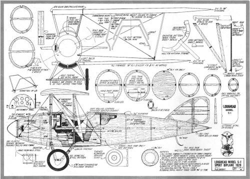 Loughead S1 - Plan sheet 1
<click for larger
version>

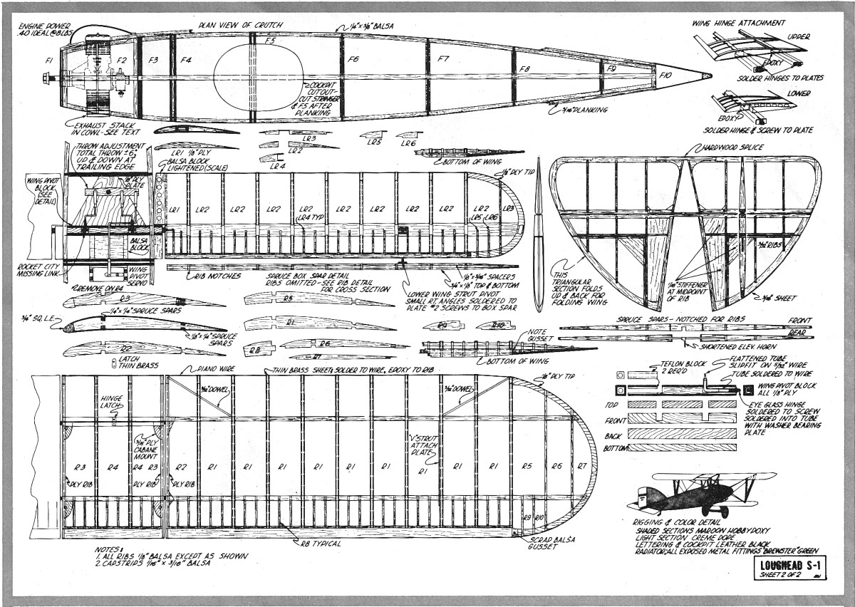
Loughead S1 - Plan sheet 2
<click for larger
version>
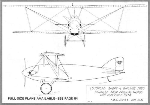 Loughead S1 - 3-view side and front
<click for larger
version>
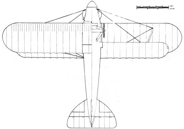
 Loughead S1 - 3-view top
<click for larger
version>
Notice:
The AMA Plans Service offers a
full-size version of many of the plans show here at a very reasonable cost. They
will scale the plans any size for you. It is always best to buy printed plans because
my scanner versions often have distortions that can cause parts to fit poorly. Purchasing
plans also help to support the operation of the
Academy of Model Aeronautics - the #1
advocate for model aviation throughout the world. If the AMA no longer has this
plan on file, I will be glad to send you my higher resolution version.
Try my Scale Calculator for
Model Airplane Plans.
Posted November 6, 2010
|