|
Website
visitor Bill J. requested that I post this article on Old Ironsides,
a Dyna-Jet-powered Jet Speed racer that appeared in the July 1970
edition of American Aircraft Modeler. These models flew with speeds
north of 160 miles per hour. On 70-foot lines, 160 mph work
out to 32 rotations per minute for the pilot, or about one revolution
every 2 seconds. That would make a lesser man too dizzy to stand
up long enough to last more than a few laps, even with the handle
being mounted to a pole to help him keep his balance. Authentic
Dyna-Jet engines are selling on eBay for over $500 when they appear.
Old Iron Sides
AMA record holder in Jet Speed was developed over several
years and much engine testing. Article covers model and jet engine
design and rework. Jerry Thomas
The most intriguing, yet frustrating, type of model airplane
is that flown in Jet Speed. Jet has the greatest unexplored potential;
but the difficulty is that its powerplant cannot be put on a block,
like a two-cycle engine, to see if a modification will increase
its speed. It must be test-flown to study the effect of air flow
on the tune of the engine. Ed Fisher and I, when going team
in Jet in 1967, started with great expectations. We succeeded in
just burning valve after valve. This was the same basic engine I
had used for years, so we felt that neither the plane nor the tank
were the cause. To double check, the engine was installed on Rollie
Hilesland's and Keith Loutocky's plane, which was running well.
The engine continued to burn valves. The flojector, which had been
used for 18 years, was replaced, and the ship turned a nice flight
of 169 mph. A few weeks later the plane won Jet Speed at the Nationals
in California at 174.86 mph.
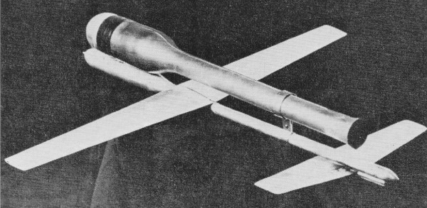
Old Ironsides Dynajet-powered Jet Speed model.

Rear view.
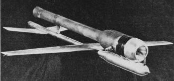
Both wood and metal versions are shown on plans. Detail above
is wing, fuselage, and control unit assembly. Wing spar is welded
steel tubing arranged so that Mono-line control wire goes out
through the tubing.
A word of caution: Model jet engines are pulse jets which run
extremely hot and should be handled by an adult. They must be
launched immediately after starting, or they will actually melt.
They burn raw white gas and make a very loud noise. But, they
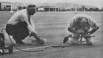
are fast, relatively simple, and fascinating. Author demonstrates
best starting position and suggests plenty of practice without
starting. Have C02 fire extinguisher handy.
Improved performance possible by very careful alterations to
valve stop. With file or lathe remove metal to permit valve
to open slightly higher and therefore longer. This step, and
a tuned front end are about the only really practical modifications
for the otherwise stock Dyna-Jet. It works, holds record.
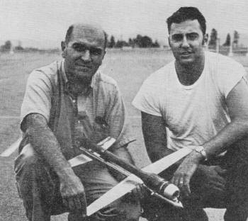
The Thomas/Fisher team. Dyna-Jet is made by Curtis Dyna-Products
of Indianapolis, Indiana
My jet flying began in 1949 with a stock Dyna-Jet - the first of
a long line of all-metal airplanes. It won first at 135 mph, and
20 years later Ed and I won first at 183.60 mph for the record with
a 028 in. line. A first attempt at modifying an engine was
to increase the valve lift by turning back the valve stop. This
removed .030 to .060 in. from the stock at the outer edge of the
valve stop, as shown on the plans. I settled on .040, which I still
use, as best for power and reliability. Beyond this, whole leaves
are lost during a flight, and valves must be changed quite often.
When running a rich metering jet, five or six flights can be had
before the edge of the valve starts to chip. This improvement, with
Mono-line, put me in the 155 mph bracket. When the valve
stop is turned to get more lift, or opening, from the valve, continue
to check with a leaf from an old valve to get as much contact between
the valve and valve stop as possible. Those who don't have a lathe
can, with some patience, file ten "flats" to get the extra lift.
Mark the .040 in. on the edge at one point. File and keep checking
until the leaf makes contact as above. Then make a template of this
curve and, using a valve to mark the valve stop for leaf position,
have at it! Take time to do a good job. Metering jets is
a critical item. To check metering jets with wire drills, I set
my standard at a No. 60 drill for a No.6 metering jet. This is done
as a check to be sure sizes are really going up or down when testing.
Metering jets have been known to vary in size for a given number.
The Dyna-Jet instructions recommend a No.4, but this varies with
the plane and tank. I used either a No.5 or No.6 for years, and
then found that this airplane and tank are best with No. 11, which
is the same size as a No. 55 drill. Testing is necessary to determine
the right size, since it varies with the tank, CG, etc. Sound is
no guide. It's done strictly by clocking the plane. Our plane is
usually going faster when it sounds erratic. When it leans out,
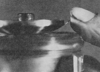
it slows down. The flojector does not have the hose connector
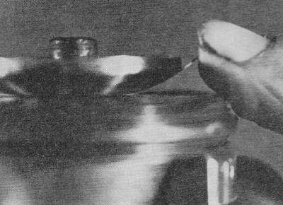
as on a stock flojector. With practice it is easier to start a jet,
since the plane need not be shifted. Note, before cutting off the
hose connector, it points between the holes and is in line with
them. This is the starting point. By taking the position shown in
the picture and looking down into the intake, it is easy to judge
by the spray of fuel, when the right place is reached. In case of
flooding, with flames coming out the tube, simply point the tube
on the tire pump at the valves. This will clear it and many times
the engine will start. To modify the tire pump, put 1/8-in. or 5/32-in.
brass tubing in the hose, and bend it slightly to come in at the
approximate angle of the original connector. A medium or small diameter
tire pump gives enough Volume of air and doesn't tire the person
pumping as quickly. Squatting over a jet model when starting
may seem dangerous, but the engine can't blow up because of the
open combustion chamber. Flames sometimes come close to the lower
extremity of the body, but in 20 years I have yet to be burned or
to set any part of my clothing on fire. When I decided to
build a tank around the intake, the result was a tank longer than
the intake in order to get the necessary Volume of fuel. After much
work, this design seemed a lost cause. Then a fellow launching the
model made a chance remark that one certain tank seemed to have
more thrust on the ground. After some thought, and much searching,
I ended up with the end of a salt shaker taped to the inside of
the intake to duplicate the length of the tank and flew it on my
regular plane. This most unscientific adaptation jumped the speed
from 155 mph to 167 mph, A turned intake, similar to those in the
picture, evolved and turned 176 mph using the old .024 in. Mono-line.
For those without a lathe, that old salt shaker and some epoxy could
make a satisfactory substitute. On the tuned intake, good
results are obtained by using the length (shown on the drawing)
of three inches from the valve face to actual intake. The venturi
opening and minimum diameter are the same as a stock Dyna-Jet. To
try tuning the engine, the overall length could be shortened by
.25 in. and a 1.5-in. inside diameter tube attached to the cowl.
Many combinations can be tried on a jet. It does takes patience
and one change at a time. Getting the most out of a jet
is not complete unless a good seal is created between the head and
tube. If the head isn't a good "rattling fit" in the tube, carefully
squeeze the tube until it is round and the head goes in easily with
no bind. Then lap the lock ring and tube face on wet-or-dry paper
until the surfaces are flat. The threads aren't perfectly true to
the faces, so any misalignment will let the ring seat flat on the
tube. It may sound like unnecessary work, but a year ago I was lazy
when the head wouldn't lock solidly so it could not be turned, and
I let it go as good enough. It meant 12 mph between that flight
and the next when the head was seated and tight. The Scotch electrical
tape that fairs the cowl to the tube is a good check on seal, because
a leak will cut the tape like a knife. The face that the
valves seat on should be flat and have no nicks from burned or chipped
valves. Find a flat plate glass window in a junk yard and on this,
with No. 280, No. 320, and No. 400 wet-or-dry paper, depending on
how deep any nicks might be, the head can be lapped in, even at
the field. Using the paper wet simplifies the job. To help
eliminate burned valves, know the metering jet sizes and run the
fastest rich metering jet possible. A No. 12 can be run but the
No. 11 is faster. Beyond a No. 12, size of the flojector hole must
be increased as it becomes the metering jet. Two types of
bodies are shown on the plans: the one used on the actual airplane;
and the other a combination of a brass tank and a wood body, for
those who don't have use of machinery or materials to make the all-metal
body. Drawings for both bodies are clear enough to build from without
detailed written instructions. Do remember to glue a piece of asbestos
along the top of the wood body. Any good piece of straight-grained
hardwood (no balsa!) will do - spruce is good. Don't get
excited about the fact that the fuel line does not go to the rear
of the tank. Believe me, it works. The shorter fuel line gives much
better running without a tendency to cut out. The fuel goes to the
back of the tank on takeoff. Since the tank is almost full, there
is no trouble getting fuel. In flight, the fuel is 30 times heavier
so it presses to the outside of the circle if the model is tracking
straight, and will go forward when the model starts to slow down.
The
tank on the actual model was a piece of spun tubing obtained from
an aircraft salvage firm, but the one shown is turned from 1 1/4-in.
24ST aluminum bar stock, as is the nose of the tank. The seal on
the tank nose is a 1 1/8-in. neoprene "O" ring which can be obtained
from a plumbing supplier. It must be just a light push fit since
the fuel will tend to swell the "O" ring. Screws holding on the
nose and the front of the skid go into the tank, but no leaking
problems have developed. The tubes are soldered to the two
1/4-in. brass screws after the screws are put into the tank nose.
Drill the 1/8-in. holes in the screws first and countersink the
nose just enough to get the screw to seat. Then file off the excess.
Wind a strand of soft wire around the end of the fuel tube and solder.
This helps obtain a seal to eliminate running lean and burning a
valve. Change the neoprene tubing for every flight session.
On the brass tank, the exploded view shows how parts go together.
Tin the edges and fit the top, bottom, and end inside the side piece
and sweat-solder together. Note the nut plate on the inside of the
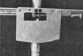
bottom of the tank. Solder it in for the front skid bolt. The material for the engine mounts and elevator horn is stainless
steel from automotive hose clamps. It's a bit hard to drill but
well worth it. This also could be used on the wing-body bracket
with the wood body, or .030-in. brass would suffice. When putting
bolts in to hold the wings, use bolts long enough to go through
the nuts and take all the load. On the 4-40 machine
screws, use hex heads or Allen bolts, which are much higher strength
than normal iron or brass screws. At least use them on the wing-body
screws, if nowhere else. Several different materials
have been shown on the plans should it be impossible to come close
to the original design. The spar on the original is 1/4-in. stainless
steel tubing heli-arc welded together for the offset. It is easy
enough to use 1/8-in. 24ST aluminum, or 1/4-in. maple for the spar.
The original tail was .06-in. magnesium, but .05- or .06-in. 24ST
aluminum could be used. Do not use a plywood tail on the all-metal
model because of the low location and dihedral necessary. However,
on the wood body this could be used. The low tail
keeps the pushrod inside the tail boom (boom is 5/8 in. thin-wall
24ST aluminum tubing) and puts the pushrod in tension for up control.
At these speeds, if the pushrod is in compression, or pushing to
get up, the pushrod bends and little or no control is possible.
There is no worry about getting "down" control with the high thrust
line. Note the 3/32-in. pushrod. The ends are carefully bent "U"
shapes, which will stay on the horns very nicely. The wings are made of .010- or .012-in. 24ST aluminum. Bending the
LE and gluing or riveting the TE is something that comes with practice
and doing. Practice with scrap pieces until satisfied with the LE
radius. When gluing or riveting the TE, make sure it is clamped
or held on a flat surface. When "potting" the epoxy tip, wax the
spar so it will separate. It pays to redo any of these steps until
satisfied with the results. The same is true with setting up the
engine. With each repetition techniques are perfected and speed
gained. We started this season turning in the low 170's, and then
just kept going faster. We finally turned 179.93, 181.75, and then
182.67 mph for our three officials, and a new record with a .031-in.
line on September 28, 1969. The starting technique
is very simple. Either standing or squatting with the model between
the legs, grasp the left wing and rest the right hand on the cowl,
pointing the brass tubing on the tire pump into the intake. With
practice, knowing where the holes in the flojector are will be easy
and a couple of pumps (slow and long) should result in a spray.
Soon it shouldn't take more than a few to start the engine. Then
just throw the hose to the side. The person with the starter box
has by then released the button and walked (or run) away, pulling
the clips off automatically. Grasp the right wing while setting
the model on the ground, making sure that the model is pointed straight
ahead. Don't get excited and release any old way. It's awfully hard
on flyers to time their leaps for getting out of the way of poor
releases. Don't waste time on the ground. The tank
on the all-metal plane allows 14 to 15 laps. We originally got 12
laps. Counting one lap to get on the pylon, it takes at least ten
laps for a clocking. We made a new nose in case Ed ever did have
a problem getting on the pylon. The fuel we use has
given those extra few mph's. After trying many things, we still
use as our basic fuel benzene with propylene oxide. By varying the
benzene propylene mixture we consistently go faster. Using straight
benzene will do an excellent job at less cost. Care
in handling these, or any chemicals, cannot be over-emphasized.
Chemicals are dangerous if not handled with common sense. Both of
these fuels are highly volatile (especially the propylene oxide).
They should be stored in a cool dry place where there is no open
flame or chance of sparks from switches, etc. With any volatile
chemical (one that evaporates rapidly), fumes develop and could
go off with a bang. This is true of paint thinner (benzene), lacquer
thinner, etc. Preferably they should be stored in their original
containers, or in dark glass or plastic bottles. Mix
fuel outside where there is plenty of fresh air. Avoid fumes, spillage
and skin contact. We mix ours at the flying site (plenty of fresh
air) so we know exactly what percentage mix we have. There is no fantastic reason for our ship's going as fast as it
has. It is simply a clean, grooving airplane that lets all the thrust
propel it forward. It is a little larger than many jet designs,
but with care it comes out between 30 to 32 oz., with the all-metal
design. Old Ironsides weighs 30 oz.
Old Ironsides Plans
<click for larger
version>
Notice:
The AMA Plans Service offers a
full-size version of many of the plans show here at a very reasonable cost. They
will scale the plans any size for you. It is always best to buy printed plans because
my scanner versions often have distortions that can cause parts to fit poorly. Purchasing
plans also help to support the operation of the
Academy of Model Aeronautics - the #1
advocate for model aviation throughout the world. If the AMA no longer has this
plan on file, I will be glad to send you my higher resolution version.
Try my Scale Calculator for
Model Airplane Plans.
|