|
The
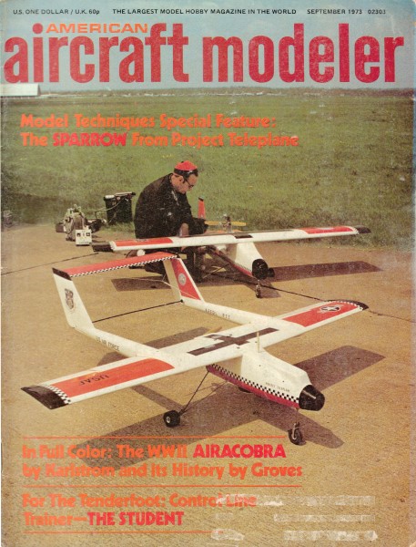
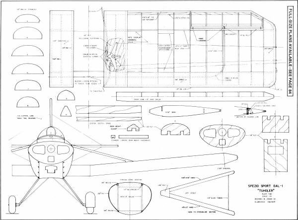
September 1973 edition of American Aircraft Modeler featured a combination
C/L and R/C, 1/6-scale model of the Spezio Sport DAL-1 Tuholer homebuilt
airplane. A 3-line systems is used for C/L so that throttle can
be controlled. Both versions call for hinged, movable ailerons and
rudder, with those surface being staked to a fixed position for
C/L flying.
Spezio Sport Tuholer
Homebuilts always make great Scale subjects. This one is a Control
Line Scale model with good stunting ability for those extra points.
It is also perfect for RC Stand-Off Scale. by Clarence Haught
The selection of a Scale subject for today's competition
is one of the most difficult tasks facing the Scale modeler. Gone
are the days when all that was required was a close resemblance
to a set of questionable three-view drawings, a non-scale glossy
finish, and lots of bent pins and thumbtacks in the cockpit. Often
the meet was won by the only ship able to struggle into the air
and complete a lap or two without the Scale crash bit. To
win in Scale today one needs a model that appears to be a real aircraft
magically shrunken to model proportions. This must be backed by
complete documentation in the form of accurate and detailed drawings,
photographs and specifications.
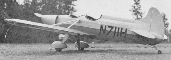
The Tuholer was chosen as a scale subject for its good
moments and ample wing/tail/ rudder areas.
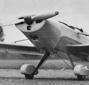
That's a real good-looking pose. Would you believe a 35 is adequate
power even for stunting? By all means use the throttle for scale
points, realistic takeoff and touch-and-go.
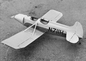
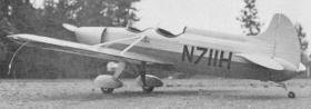
How about that nifty scale tail wheel? It's worth several scale
paints. Cockpit is simple-it needs the full pilot and instruments
treatment if you can avoid weight buildup.
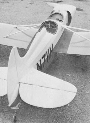
Symmetrical stunt airfoil is evident in this view of the model.
What it costs in lost scale points is easily made up by optional
maneuvers. Ailerons and rudder are fixed for flight unless you
fly it RC.
By visiting the larger meets and reading model magazines it becomes
apparent that a new trend is developing: the scale homebuilt. There
are many good reasons for this. Any aircraft built in the home workshop,
for example, can be duplicated part by part by the modeler if he
so desires. There are usually no elaborate fittings or forgings
to duplicate and similar materials are used in constructing the
model. Another advantage is that authentic scale documentation is
usually available from the original designer! Also on the plus side
are the variations seen on given homebuilt designs such as cowlings,
wheel pants, etc. Be careful on this one, however-you must be able
to document your version. If the variation desired is difficult
to document, then you are better off building a scale model of the
prototype. You may, however, exercise some freedom in paint schemes
and numbers as long as the original design is utilized.
Before selecting the Tuholer as a subject, I researched eight airplanes
in this general category. I settled on the Tuholer for a number
of reasons. My first interest in Control Line flying is stunt and
I wanted a subject with aerobatic capabilities. The Tuholer has
ideal moments and nearly 500 sq. in. of wing area. With an adequate
engine this plane will not be aerobatically disappointing. In fact,
the ship flies like a typical non-flapped stunter, and is smooth
and responsive. I made two scale deviations on the original:
a symmetrical airfoil and an enlarged horizontal stabilizer. The
plan shows the scale stabilizer length, but if you are not interested
in aerobatics, the ship will handle well with the smaller tail surface.
Deviations from scale must be listed in your documentation and will
cost you a few points; they are minor compared to the aerobatic
flight points possible with the slight modifications. While
we're on the subject of scale documentation, the winter 1971 issue
of Air Trails Sport Aircraft is a good source and the October 1966
issue of Sport Aviation, the official publication of the
Experimental Aircraft Association, has a lengthy article on the
Tuholer. Both issues are available and have three-views with dimensions
as well as an excellent cutaway view giving many usable details.
Plans including many photographs are available from designer Tony
Spezio for construction of the real airplane. There are
several features any scale model in this category should include.
In general, adhere to scale rib and stringer locations as well as
proper control hinge locations. Fabric areas should be silk-covered
and finished with enough dope to fill sufficiently, but the fabric
weave should be visible. Sheet metal covered areas should be well
filled with the proper "edges" apparent. Any sheeted areas, such
as leading edges, should be duplicated and trailing edges made as
unobtrusive as possible. The cockpit should have moveable rudder
pedals and sticks that follow control movements. Scale structure
should be visible in cockpit area; instruments, switches and secondary
controls should be properly located and duplicated. Give careful
attention to tail-wheels as many points can be added here. Throttle
control on the engine is well worth the effort, however the added
drag of the third wire will make aerobatics risky unless an engine
in the 40-45 class is used. You will have to be the judge.
Construction The Tuholer is not a beginner's
project so this will not be a glue-stick-A-to-former-B article.
My comments on construction are limited to specific details which
may be of help. The fuselage should be started first and
is simply sheet sides attached to the plywood former and engine
mount assembly. Stringers and sheet fillers complete the sides.
Formers in the after fuselage are built up from 1/8 x 1/4" strip
stock and the sides are joined at the tail post. The fuselage construction
should stop at this stage to allow easy assembly of wings, tail
surfaces and landing gear. The wing is built next. The inboard
center section rib spacing is dependent upon actual fuselage width
so this dimension may need to be altered on your plans. The wing
is completely assembled without left upper center section planking
(over bellcrank) and installed as a unit into fuselage. Simply notch
fuselage from the bottom for spars and slip wing upward into fuselage
against the 1/4" sheet filler. Add lower filler sheet and wing installation
is complete. Two suggestions are in order here:
Drill the front spar for landing gear J bolts and notch front spar
to accommodate torque tube prior to assembly; reinforce bellcrank
mount with scrap balsa gussets wherever possible, as this is a highly
stressed area. You may wish to notch the plywood center section
spars for the bell crank mount. The tail surfaces are
made of 1/4" sheet with nylon thread used to simulate ribs. Silk
covering applied over the balsa and simulated ribs will provide
a scale appearance without the delicacy of a built-up surface. You
will note an extra elevator horn on top of the stabilizer as well
as the regular horn below. The upper horn provides correct stick
movement in the cockpit in relation to elevator movement. The bellcrank
is attached to the lower horn by means of a flexible cable in a
nylon tube. Anchor the nylon tube in several places. If threaded
clevises are used for connections, solder them in place after final
adjustment to prevent working due to vibration.
All
cockpit detail and controls should be added at this time. The "backside"
of fabric covering in the cockpit area can be simulated with Silkspan
doped to the balsa sides. 1/32 x 1/16" balsa laid flat will simulate
stringers. Structural tubing is l/S" dowel finished with zinc chromate
Aerogloss. Rudder pedals are soldered up from l/S" brass tubing
and hinged to the 1/32" plywood floorboard. Front and rear pedals
are linked with piano wire to a 1/16 x 1/4 x 3" dural strip pivoted
beneath the floorboard at the rear. At final assembly, 018 control
line cable completes the hookup to the rudder horns. The
torque tube assembly is also made from brass tubing soldered together
and attached to the floorboard before installation as a unit into
the fuselage. Coordinate this assembly step with the landing gear
assembly. Cockpit seats are 1/32" plywood. Don't forget
seat belts. Make the buckles out of sheet aluminum and the webbing
out 1/2" braid from the sewing shop. Commercially available
instruments may be used. I used World Engines instruments in the
rear cockpit only. However, if you purchase instruments, you must
list them in the documentation under "parts not constructed by builder"
and this will cost you points. They can be made using photographic
reproductions of the faces with frames fashioned from bits of metal.
Fuselage construction resumes after all controls and cockpit
details are complete. There are no stringers on the bottom. The
area around the cockpits is metal on the real ship and is made up
of 1/4 x 1/8" round edge planking and finished to simulate a metal
surface. If you mask around the edge of sheet metal areas prior
to building up the finish with filler, you will obtain a slightly
raised edge, which can be carefully beveled to simulate a metal-to-fabric
joint. This should also be done where the side stringers meet the
1/4" sheet filler in the area of the wing leading edge. Cockpit
coaming is 1/4" neoprene tubing with a quarter of its cross section
cut away to allow a good fit to the cockpit edges. Attach with epoxy
glue. Wing struts should be made up and fitted to the model
utilizing round toothpick alignment dowels. They should be finished
separately from the model along with the cowling and attached with
epoxy after the finishing process. The cowling on this ship
attracts more attention then anything else, but it was actually
quite easy to construct. Attach top and bottom balsa blocks to former
No.1. Two 1/8 x 1/4" vertical members hold them in alignment temporarily
as shown in the typical cowling cross section. Slip the cowl in
place and shape the top and bottom blocks. Next add 1/4" sq. spruce
to both edges of the balsa blocks. Allow clearance for the 1/32"
plywood side pieces at the top. Glue plywood side pieces to top
block with epoxy. Wet plywood and pull around former No.1 and down
to bottom block. Secure with masking tape and allow to dry at least
24 hrs. The tape is then removed and the formed plywood cowl sides
are glued in place; four No.3 1/4" metal screws are added to simulate
Dzuz fasteners and help secure cowl sides. A front block and a scoop
are added to complete the cowl. Attach cowling with bike
spokes and one alignment dowel as shown. No cutouts were made for
exhaust or needle valve on the original. The inside of the cowl
was coated with epoxy glue for a sealer. The cowl is removed and
the engine is started and adjusted prior to going to the flight
line. The cowling is replaced prior to flight and the engine is
restarted while you hold the model inverted in stunt fashion. The
exhaust will echo inside the cowl and provides a realistic sound.
There is plenty of air circulation to carry .away the exhaust and
to cool the engine. Some attention should be given the tail-wheel
assembly. Look at some full scale tail-wheel assemblies and try
to du-plicate them. A simple wire sticking out with a wheel attached
will detract greatly from the scale appearance. I used 1/16 x 1/4"
aluminum for "springs" and small copper wire with solder flowed
around it for "clamps." The swivel bearing was adapted from an RC
nylon tail-wheel bracket. Take your time on the finish.
Silk seems to handle best if it is drawn down over a previously
doped and sanded structure and adhered with a brush dipped in thinner
to activate the dope underneath. After water shrinking,
apply enough dope to seal the fabric but not so much that the fabric
effect is lost. Here again it will pay to look at some real aircraft
finishes and try to simulate them. Very few have hand-rubbed glossy
finishes on fabric. However, some homebuilts will, so you may want
to weigh this decision. Flying Be
sure of the center of gravity location. It should be two in. behind
the wing leading edge with the fuel tank full. If the CG is too
far forward, you have takeoff problems on rough fields as the tail
comes right up on takeoff. Since this ship has moveable
ailerons and rudder, they will have to be locked before flight.
I tie the rudder over hard right with rubber bands between the fuselage
lift handle and the rudder horn. Be sure this doesn't bind the elevators.
For initial flights you may wish to set the ailerons to assist in
maintaining the line tension (I use hat pins for this).
You will find the ship easy to fly and, if you have throttle control,
beautiful touch-and-goes are possible. Just set the model up nose
high with a little power and gradually reduce throttle as she settles
in. Prior to flying aerobatics with your Tuholer you will
want to cover your bets by careful preflight checks. First of all,
the flying surfaces must be in perfect alignment with no warps present
in the wing. A warp that will aid in maintaining line tension in
normal flight will work against you in inverted flight, possibly
causing you to lose the airplane due to slack lines. If
your ship weighs over 55 oz., you are getting near the maximum for
stuntability especially with a three-line control setup. The added
drag of that third line really shows up in aerobatics. Use the minimum
wire diameter allowed by the rules and 55 ft. length. A
good strong 40 is necessary for aerobatics. Set it up with about
1½° of offset to the right to insure good line tension. The ailerons
will, of course, have to be secured in the neutral position. I use
a 11 x 5 prop but the ship does fine on a 10 x 6. The longer prop
looks better with such a wide cowling and is nearer scale diameter.
Stunting a scale ship may seem sacrilegious but, if the
model has the capability, why not garner those extra points offered
in the rulebook? These maneuvers consist of loops, wingovers, figure
eights and inverted flight. If you're not an experienced stunt flier,
do the maneuvers you can and let the rest go. I am hesitant in recommending
the vertical wingover, however. This is an extremely simple maneuver,
but I feel it places the model in undue jeopardy. Engine failure
or even hesitation is more critical in this maneuver than the others
because line tension is marginal at best and, if the wind is blowing,
it tends to be worse. Loops and eights are done directly downwind
with line tension aided by the wind. I nverted flight should be
entered downwind with subsequent recovery downwind also. Generally
speaking, inverted flight is safe in moderate wind which shows little
or no effect in normal flight. Figure-eights in scale should
be the type known as lazy eights and not the type shown in the aerobatic
rules. In fact, this maneuver is one of the best training maneuvers
for the beginning stunt flier as it gradually leads him into inverted
flight and overcomes his fear of giving "down" control at the handle.
The maneuver is entered from a shallow dive adding up elevator
until two-thirds of a normal loop is completed. The elevator is
momentarily neutralized resulting in a shallow inverted dive. Down
elevator is then applied to accomplish the "outside" portion of
the maneuver recovering in level upright flight; this results in
a lazy or stretched out horizontal figure-eight. Whenever you fly
aerobatics, be prepared to abort the maneuver at any time and return
to level flight even if it means inverted level flight with a dead
engine. Inverted dead stick landings are hard on rudders, but attempting
to get right side up without sufficient speed, altitude and line
tension usually results in a serious crash. Even if you
can resist aerobatics you'll find the Tuholer one of the greatest
flyers yet to invade the scale circle. Several of my friends have
suggested that the Tuholer would make a nice RC model. I must agree
and plenty of radio space is available in the wing center sections
and under the seats. Either way I think you'll like the Tuholer.
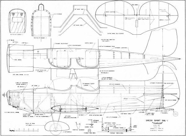
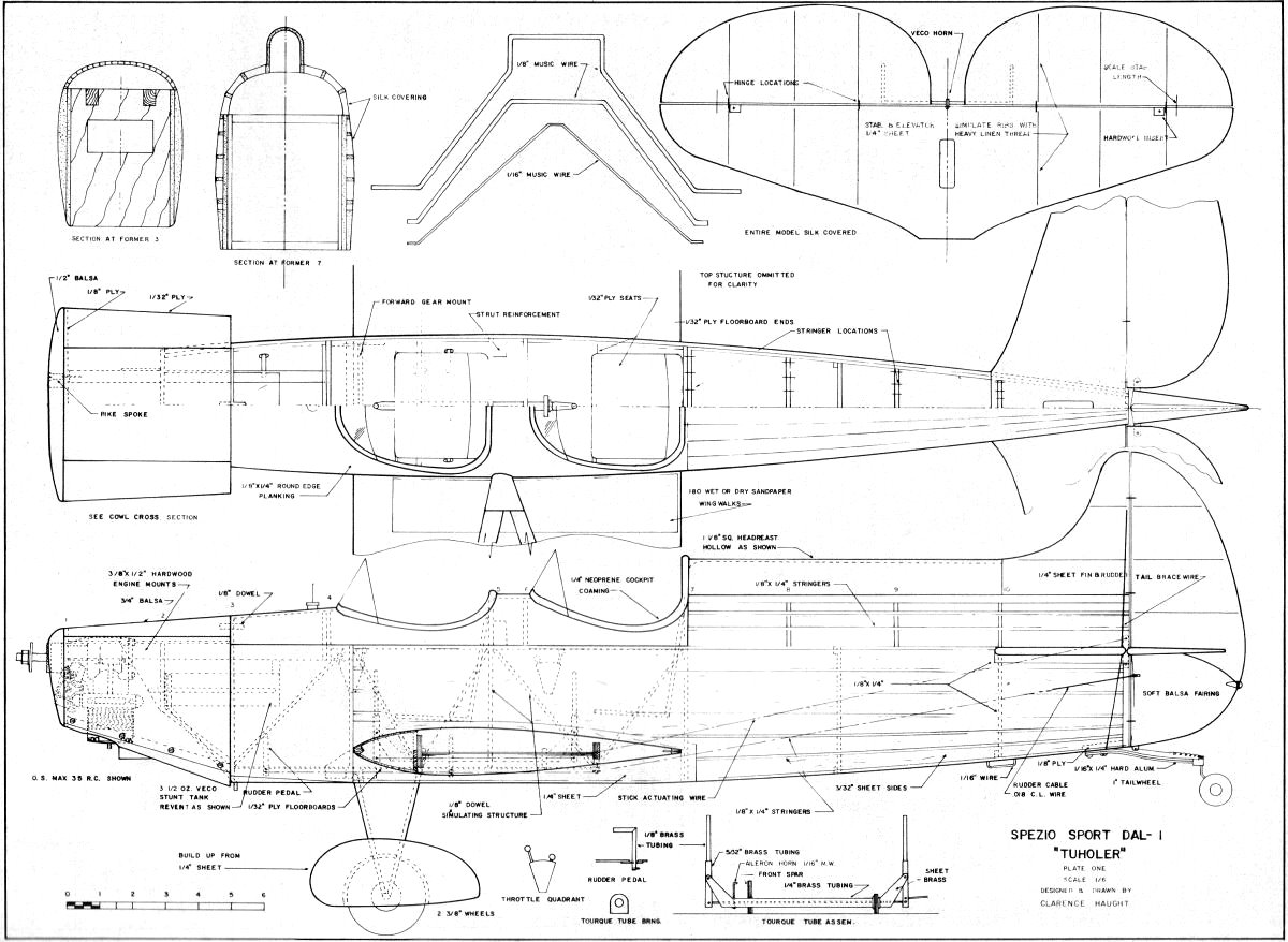
<click for larger version>
<click for larger version>
Notice:
The AMA Plans Service offers a
full-size version of many of the plans show here at a very reasonable cost. They
will scale the plans any size for you. It is always best to buy printed plans because
my scanner versions often have distortions that can cause parts to fit poorly. Purchasing
plans also help to support the operation of the
Academy of Model Aeronautics - the #1
advocate for model aviation throughout the world. If the AMA no longer has this
plan on file, I will be glad to send you my higher resolution version.
Try my Scale Calculator for
Model Airplane Plans.
Posted November 20, 2010
|