|
Website visitor Bob P. wrote
from New Zealand to ask that I scan and post this Wizrod 350 article and plans from the
July 1972 edition of American Aircraft Modeler. Wizrod 350 is a ½A freeflight
job designed by Ron St. Jean. Bob has been a fan of St. Jean's models from
the 1950s and 60s, and wants to see how the designs progressed into the 1970s. Billed
by the author as "an uncomplicated high-performance FF power design," the Wizrod 350
would make a good subject for a vintage craft.
Wizrod 350
By Ron St. Jean
As its name implies, the Wizrod is a combination of the best of two other models designed
by the author several years ago, the Wizard and the Ramrod. Of the two models, the Ramrod
was the easiest to trim out and the most forgiving when mistakes were made, although
both were exceptionally easy to fly compared to other designs available. So in making
the combination, we started with the Ramrod configuration as a basis.
When you combine the best of a wizard and a ramrod, here's what you
get - an uncomplicated high-performance FF power design.
The Wizard had such a long fuselage that it reminded one of a gangly teenage boy.
Because of this long fuselage, the Wizards tended to flex when in flight, the tail sometimes
appearing to wobble from side to side as the fuselage twisted. Actually, this characteristic
did not harm the flight pattern, but probably did spook away a few potential Wizard builders.
Another unwanted characteristic of the Wizard was its occasional tendency to tail slide.
If you ever saw one come half way down from shut-off-tail first - before completing the
stall, you'd remember it. But don't let us sell the Wizard short. Its great contest potential
is perhaps best attested to by Lee Polansky's phenomenal Class A Open record of 94:19!
And this was done with the 1/2A version with an 051 engine, breaking his own previous
Class A record of some 70 minutes set with the same model.
Despite the innumerable trophies that the Ramrod brought home for its owners over
the years, it was not quite perfect either. The wing airfoil was not optimal, and every
once in a while a Ramrod would zero out, normally coming straight in under power at a
very high speed. It was finally discovered that this tendency to zero out was due to
the wing's center of pressure being slightly behind the lateral twisting line of the
wing. Thus, under conditions of high loading, a twist in the wing was introduced which
was similar to adding negative incidence. Needless to say, if any Ramrod, and especially
a hot one, were tail heavy and thus short on incidence to begin with, it would be dangerous
to fly, as just a little negative wing twisting could spell disaster.
This
phenomenon of wing twisting was best demonstrated on a Ramrod 600 several years ago.
We had been flying this particular 600, which was rather heavy, with a 29 engine for
some time, with no complaints. Just for fun one day, we substituted a hopped-up 35 for
the so-so 29. The first flight, with the 35 running at a fast four-cycle, was quite normal
with an average nose-up-under-power tendency. But when this hot 35 was leaned out on
the second flight, a most amazing thing happened: the 600, which had been launched straight
up, climbed to perhaps 150 feet, slowly nosed over into a dive, came straight down, and
pulled out upside down! It had done an outside loop! Continuing its inverted climb at
about a 20-degree angle, the Ramrod started a slow roll, which was nearly completed when
the engine shut off, the model gliding in normally, just as if nothing had happened!
Shades of Eddie Rickenbacker - we had almost done an inverted Immelmann with a free-flight
gas model! Visibly shaking from what we had just witnessed, we resolved never to fly
that model again, so once we were home, it went up into the attic.
Another example, this one illustrating a positive use of the phenomenon described,
is Lee Hines' Sweepette hand-launched glider design. Lee discovered that his gliders
performed better with a highly swept-back wing, probably because they were getting higher
on launch. In effect, he had a variable-incidence glider. That is, the center of pressure
was well behind the lateral bending line of the wing, the incidence coming out during
the launch burst, but returning for glide stability.
But back to the Wizrod: The first departure from the Ramrod design was to utilize
the Wizard tapered wing-tip configuration to eliminate the old tendency to zero out.
The Wizard wing airfoil was used with its free undercamber, which had proven superior
to the old 10% flat-bottom of the Ramrod. We use the term "free undercamber" here because
the Wizard and Wizrod wings are built as 8 1/2-9% thick flat-bottom sections that gain
1-1 1/2% of undercamber during building and doping due to the rib-over-spar type of construction.
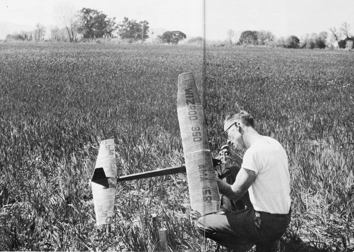
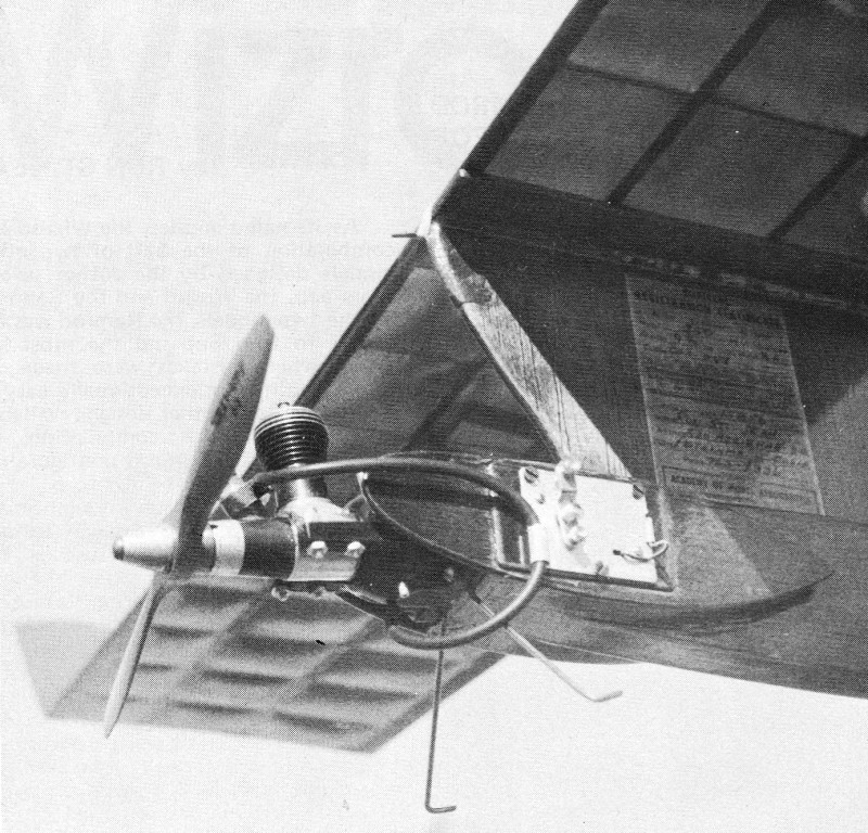
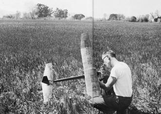
High-revving Tee Dee 049 swinging a RevUP 633 prop pulls Wizrod way
up. Cox tank mount is used.
In line with the lessons learned from the extended Ramrods, the Wizrod wing was also
extended to the same degree as the Wizard, and the fuselage was also lengthened in accordance
with the old formulas. But unlike either the Wizard or extended Ramrods, the stabilizer
was extended, with an increase in aspect ratio, so as to maintain the 43%-of-wing-area
relationship found in the original Ramrod.
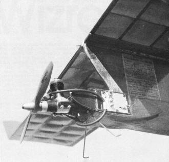
With the exception of the new nose, which was designed around the rectangular Tee
Dee 049 tank mount, construction is the same as in the Wizard, because it proved to have
no weak spots and was generally simpler than the Ramrod.
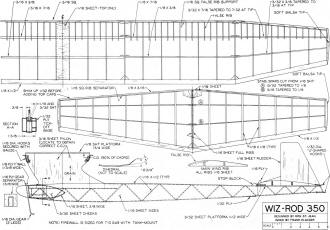
The Wizrod magazine plans are one-fourth full size, so scale up accordingly. Better
yet, send for the full-size plans (see page 84). Should you prefer to build the model
in other than the 1 1/2A size, consult the accompanying table for areas and corresponding
factors to use in converting the "350" dimensions. If working from mag plans rather than
full-size ones, use the factor in the fourth column, rather than that in the third, to
get your full-size dimensions.
Construction
Because the Wizrod fuselage is basically the profile type, it is simple to construct.
Begin by cutting out one fuselage side from 1/16 x 3" medium balsa. Align the balsa behind
the plan and mark the balsa by pushing a pin through the plan and into the 1/16" sheet.
Besides the outline, make marks for the firewall and the longeron that goes under the
pylon. Note that the firewall has a 10-degree downthrust angle built in. Duplicate the
second side by using the first as a pattern. Pin the first side to your workbench (the
plans are no longer needed) and add the longerons, followed by the diagonal crosspieces.
All are 1/16 x 1/2". Be sure to eliminate the crosspiece under the front of the stab
platform that would otherwise interfere with proper DT action. When dry, sand lightly
to eliminate any unevenness between the longerons and crosspieces, then add the second
side.
When dry, lift the fuselage from your workbench, block-sand the front to insure there
will be no sidethrust and that it is flat, then cut out and add the firewall. The two-piece
gear separator is then cemented directly to the firewall. Install the tank-mount on the
firewall with 2-56 or 3-48 machine screws, using epoxy cement to glue the nuts to the
rear of the firewall. Use care to insure that none of the epoxy gets on the screws. The
3/32" side cheeks are best cut out as were the fuselage sides. Mark one of them for the
Tick-Off timer, using the left or right, depending on your preference. After the timer
hole is cut, glue 1/16 x 3/8" pieces to the inside of the cheek to make a box for the
timer. The 1/16 x 3/8" balsa needed to separate the cheeks from the fuselage is best
cut from 1/16" sheet, the grain of the wood being cross-wise to accommodate the curves.
Cement this material to each cheek only after it has been carefully cut, assembled, and
sanded to proper size. Finally, the cheek assemblies are cemented to the sides and firewall.
(An alternate procedure here is to glue the cheeks to the firewall and then add the curved
3/8" wide pieces to fit.) Now add the 1/32" plywood Tick-Off timer mount. Cement the
tail platform and stop block to the rear of the fuselage, and add the 1/32" U-shaped
piano wire to the bottom for a tail hook.
Cutout and assemble the 3/16" medium sheet balsa pylon, and add the platform, hooks
and gauze. Shape and sand, but do not assemble the pylon to the fuselage at this point.
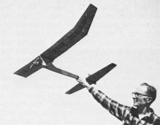
Author's Wizrod 350 model is bright Jap tissue covered to help the
timers and chase crew keep it in sight. This plane is for the trophy hound!
The Wizrod wing offers nothing unusual or new - just the typical rib-over-spar construction.
Accordingly, only a few construction hints will be provided here. The rib-to-spar fit
should be snug, but not forced. Ribs that are too loose may result in a wing with excessive
undercamber, while force-fit ribs might cause a convex rather than a concave lower surface,
which would degrade performance considerably. The two center ribs, in order to accommodate
the 1/16" planking, need to have their top cambers reduced by 1/16". The 1/16" square
false rib support glued to the bottom rear of the leading edge should be immediately
cleaned of any cement fillet which might squeeze up, in order that the false ribs added
later will fit properly and not be held up. This is easily accomplished, as each strip
is put in place, with a square-ended piece of scrap balsa.
Making a main rib template or pattern out of thin aluminum (or plywood, as a second
choice) will be a useful tool in cutting out both the ribs and false ribs. To make the
different-sized wingtip ribs, first layout the correct length and spar locations for
each rib. Then place the main rib pattern on the balsa, with the leading edges together,
and lower the pattern's trailing edge until an arc drawn across the top camber will intersect
a point 1/8" higher than the lower camber at the end of the rib. Draw the arc across
the top camber or, if using a metal template, cut the rib directly. The correct spar
depths are most easily figured by marking, on the already-cut spars, the places where
the ribs will intersect, laying the spar upon the rib in such a way that the point on
each where the eventual joint will be made come together, and making a mark for the top
of the spar. The corresponding rib for the opposite wing half can then be duplicated
from the first one made in this way.
Begin the stabilizer by pinning down - over a piece of waxed paper, of course - the
leading edge, notched trailing edge, and bottom cap strips of 1/16 x 1/8". Next add the
single large piece of 1/16" sheet at the center of the leading edge (which extends into
both right and left halves of the stabilizer, with wood grain spanwise), followed by
the two full ribs. Since the fin, dorsal fin, and plywood rubber band hook are later
cemented between these two ribs, it is a good idea to make sure they are separated from
each other by inserting scrap 1/16" sheet between them while the glue is drying. Next
add the two small pieces of 1/16" sheet at the center of the leading edge, noting that
the grain should run fore and aft, as opposed to that for the single piece underneath
them. The two gussets of scrap 1/8" sheet are now added, as are the 1/16" square rib
separator at the leading edge (clean off excess glue, as was done for the wing). and
the spars. Scrap 1/16" sheet is used on the spars at the center to increase strength.
At this point only the top cap strips are lacking; before they are cut and glued in
place, all joints must be permitted to dry, then the leading edge unpinned and shimmed
up 1/32" with scrap balsa, and then re-pinned. This will help insure that the stabilizer's
bottom surface is slightly convex - a condition required for good, longitudinal stability
(the ability to recover from a stall quickly). Add the fin, dorsal fin, and rubber band
hooks only after the stab is covered, but before it is doped.
Once the model is complete except for the pylon being glued to the fuselage, assemble
the ship and locate the CG. The chances are good that the pylon will have to be further
aft than shown on the plans in order for the CG to be in the proper place. Assuming this
to be the case, slide the pylon back on the fuselage until the CG does fall in the proper
place in relation to the wing and then cement it to the fuselage at this point.
Next, check for wing and stabilizer warps by sighting along the bottom of the surfaces.
Ideally, the stab should be flat, but a little twist won't hurt anything. The wing should
be warped noticeably but not excessively for a left turn. It does not matter whether
the left panels are washed out, the right panels washed in, or if all the twist is in
the center section. Just insure that the left-turn warp is somewhere present in the wing
by steaming or holding it over an electric range at low heat and twisting the surface
in the desired direction. Over-warp by about 100%, as there will be a significant return.
Visually check the model to make sure there is no engine side thrust. Slight right
thrust is tolerable, but any leftthrust should be eliminated by placing washers behind
the left side of the tank mount. When the back of the tail is keyed to the stab platform
with a piece of 1/8 x 1/4" scrap balsa on each side, there should be a slight fin offset
to the left. The plywood rubber band hook at the front acts as not only a key, but also
as a DT limiter. To achieve the latter function, cut the slot needed to pass the hook
through the stab platform a little long in the direction of the tail. The longer this
slot, the greater the DT angle, which should be about 45 degrees. Finally, shim up the
left side of the stab platform 1/32" to 1/16" to induce a left-hand glide circle.
Flying
After the surfaces have been allowed to cure out for about one week after the final
bout with the tea kettle or stove, take the model and some shim balsa to the field and
toss your new Wizrod around a bit. If you have eyeballed the stab tilt well, the only
thing left is to see if an incidence change is needed to achieve a normal gliding attitude.
After you have verified glide circle and incidence, and have gotten the feel of the model,
try a few test glides with succeedingly more zip, being sure the left wing is low to
avoid a stall. In this way there is little possibility of having the model act up after
fueling off on the first power flight. Besides, it gives one a little HLG practice.
Make the first test flight with a short engine run, the prop on backwards, and the
engine running rich. There should be a definite nosing-up tendency and a shallow (15-30
degree) right bank. If not, make the needed adjustment and try again. In any event, you
should have your new Wizrod full bore and right in the groove by the third or fourth
flight ... we wish you well.
Wizrod 350 Plans
Notice:
The AMA Plans Service offers a
full-size version of many of the plans show here at a very reasonable cost. They
will scale the plans any size for you. It is always best to buy printed plans because
my scanner versions often have distortions that can cause parts to fit poorly. Purchasing
plans also help to support the operation of the
Academy of Model Aeronautics - the #1
advocate for model aviation throughout the world. If the AMA no longer has this
plan on file, I will be glad to send you my higher resolution version.
Try my Scale Calculator for
Model Airplane Plans.
Posted November 20, 2014
|