|
It was a lot of work to put together a radio control model of any sort in 1953,
but the complexity of this paddlewheel model boat seems excessive. It claims, through
careful consideration and design, to have overcome to main two obstacles of entering
the remote control model realm - a need to possess expert modeling skills and a
need to possess an amateur radio operator license. Obstacle one is (ostensibly)
overcome through simple boat and electronics construction, and obstacle two is overcome
through use of a radio that operates in the unlicensed Citizens band. I'll give
them the second, but at least to today's ARF and RTF hobbyist population, the first
is still way beyond the ability of most enthusiasts. You're probably tired of hearing
it if you read my notes often, but the fundamental lack in hands-on craftsmen in
the country (all countries) is pretty pathetic. Evidently such abilities aren't
required for society to progress... but that depends on your definition of progress. Model Boat for the 27 mc. Citizens Band
By Hartland B. Smith, W8VVD
Here it is! A "Citizens Band" radio control system, easy to build, simple to
operate, and no license exam required!
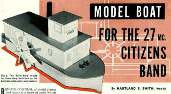 Fig. 1. The "River King" ready
for launching. Switches on the bow are for receiver and motors.
|
Remote control of model planes and boats is a facet of radio which has long
intrigued many hams and experimenters. However, two factors have kept most fellows
from taking up this branch of the hobby. In the first place, as each succeeding
article on the subject has appeared in contemporary publications, the models, the
radio gear, or both have become more and more complicated. Secondly, the possession
of a radio operator's license has been a prerequisite to the operation of radio
control equipment. Since a large number of licensed hams aren't expert model makers
and since many model makers lack operator's licenses, only a few people have so
far had the opportunity of experimenting with radio control systems.
The "River King" was designed expressly to meet these two problems. It requires
no particular skill to construct and uses a simple one-tube receiver. Any U.S. citizen
over 18 can, without taking a technical exam, obtain the necessary Citizens Radio
station license for the transmitter.
Although the FCC's rules governing the Citizens Radio Service have allowed radio
control on the 460-470 mc. band since June 1, 1949, the equipment specifications
for these frequencies have been so stringent that only commercial transmitters have
been practical up to now. A recent amendment to the rules, however, has opened the
door to inexpensive home-built gear operating on 27.255 mc. Transmitters using this
new frequency are designated as "Class C" Citizens Radio Stations and, when registered
with the FCC, may be used without an operator's license. The owner takes out a license
for the equipment by a fairly simple procedure outlined toward the end of this article.
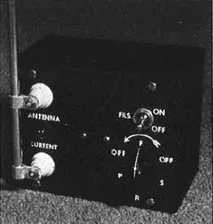 Fig. 2. The 27-mc. "Citizens Band"
transmitter, built in a 3"x4"x5" utility box. The batteries are also housed in this
box.
|
Unless a fellow is a dyed-in-the-wool model maker, he finds it hard enough to build
an airplane that looks like a plane, let alone flies. On the other hand, almost
any piece of wood will float. Thus, a model boat appears to be a logical beginner's
choice for a radio control project. Since a flat bottomed hull with no complicated
curves to cut makes for easy modeling, a side-wheel river steamer using this type
of hull is a suitable prototype from which an approximate copy may be constructed.
The one-tube superregenerative receiver used in the boat is designed around a
Raytheon type RK-61 subminiature gas triode. With the exception of the plate relay,
all receiver parts are standard and can be readily obtained from any well-stocked
jobber.
The plate relay I used came from a surplus BC-645 and was originally sealed in
a cylindrical can with a 5-prong plug. After being removed from its housing the
relay was mounted on top of the receiver chassis. If you can't locate one of these
relays, I would suggest that you obtain an 8000 ohm Sigma type 4F. The latter is
still available quite reasonably on the surplus market.
The RK-61 has tinned leads in place of base pins. It can be held in place with
a small clamp and the leads may then be soldered directly into the circuit. Use
a clean, hot, well-tinned iron, preferably one with a small tip. Do the job neatly
but as quickly as possible so that too much heat will not be conducted into this
small tube.
The receiver filament switch, S1 and motor switch, S2 are
mounted on the deck, forward of the cabin, and can be operated without removing
the superstructure. Two switches are used so that the receiver and motors may be
run independently. It is difficult to make precise receiver adjustments while the
paddle wheels are revolving.
The smoke stack, an 18" length of 3/4" aluminum tubing, acts as a receiving antenna.
While much shorter than a resonant 11-meter antenna, it picks up enough signal to
produce reliable model response several hundred feet from the small transmitter
to be described. Greater antenna length will increase the working range of the model,
but there seems little point in operating the device very far from the observer.
After all, most of the enjoyment in running the boat comes from being able to watch
it maneuver. Beyond two hundred feet, it looks pretty small.
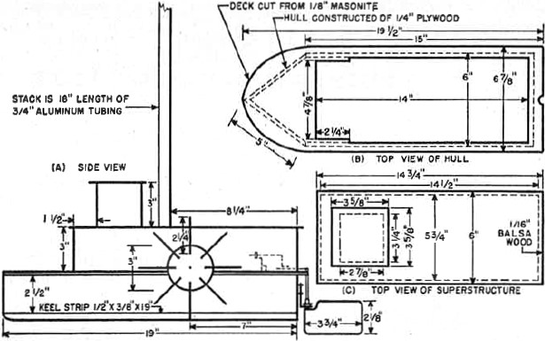
Fig. 3. Construction details of the "River King" radio-controlled
river boat. The superstructure is thin balsa wood. the hull 1/4" plywood and the
deck Masonite. The tall aluminum "smokestack" acts as the antenna for the receiver
in the hull.
The electrical circuits and mechanical linkages used in many radio control systems
are quite complex. Transmitters sometimes utilize intricate modulators and keyers
which send out specially coded signals that must be translated by the receiver into
the proper model maneuver. Actually, it is possible to obtain several different
and interesting model responses by merely turning a transmitter carrier on and off.
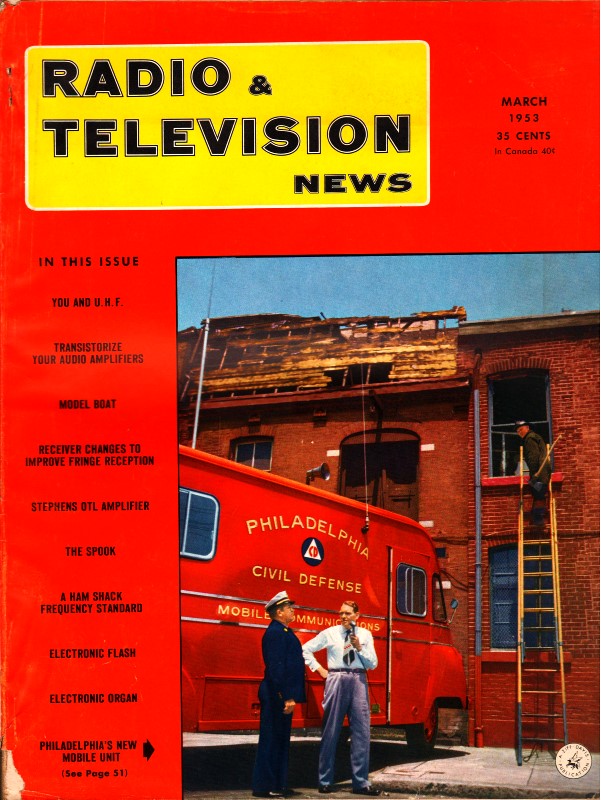
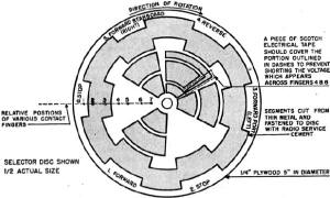 Fig. 4. Pattern for the rotary
stepping switch in the receiver. The base is 1/4" plywood, 5" in diameter. The switch
segments (shaded areas) are thin sheet metal A 1/4" hole is drilled in the center
for the shaft, which also drives rudder crank.

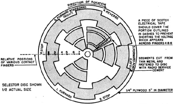
Fig. 5. Top view of the hull, with the superstructure removed. Placement of parts
can vary according to materials on hand, but weight should be evenly distributed
and heavy items such as batteries kept low in the hull. The paddle shalt is made
from two 1/4" carriage bolts. At extreme right is the old dial pointer used as coupling
between the rudder and the slotted "tiller:" which is about 4 1/8" long and is driven
by a homemade crank on the selector switch shalt. Both the rudder and selector switch
shafts and bearings are made from old Volume controls.
|
Examination of Fig. 6 will reveal that the plate relay of the receiver acts as a
s.p.d.t. switch. Since the receiver's plate current drops when a signal is picked
up, if the transmitter is on, the relay is open and contact Y receives 1 1/2 volts
via the relay armature. When the transmitter is switched off, the receiver plate
current increases and the relay closes. Contact X then receives 1 1/2 volts. Relay
contact X is connected to finger 1 and contact Y to finger 3 of the rotary selector
switch. One lead of the selector switch motor is grounded. The other lead runs to
finger 2 on the selector switch. When the transmitter goes on, the switch motor
circuit is completed via the relay armature, relay contact Y, finger 3, a segment
on the selector disc, and finger 2. The switch motor receives power and the selector
disc turns. It can only go a little way, though, because the connection between
fingers 2 and 3 is soon broken due to the shape of the segment on the selector disc.
When plate voltage is removed from the transmitter the relay closes and the switch
motor is again energized, this time via contact X, finger 1, a different selector
segment, and finger 2. The selector disc turns until finger's 1 and 2 are no longer
connected with one another through the disc segment. This time when the disc stops,
fingers 4, 5, 6, and 7 make contact with segments which connect the paddle motor
to battery, B4. Depending on what polarity voltage is applied to this
motor by the arrangement of the segments, the paddles will drive the boat either
forward or backward. If no segments are in this particular position, the paddle
motor, of course, stops. At the same time the selector disc turns, the steering
arm also turns, thereby changing the rudder position (see Fig. 5).
With the segment layout shown in Fig. 4, there are six possible maneuvers: 1.
Forward straight. 2. Stop. 3. Forward port (left). 4. Reverse straight. 5. Forward
starboard (right.) 6. Stop. This arrangement is sufficient to provide a great deal
of entertainment while maintaining a relatively simple system. The sequence of operations
is such that when going from one desired maneuver to another, the undesired positions
through which the selector must pass have little effect on the action of the craft.
For example, in going from forward straight to forward starboard, it is necessary
to go through positions 2, 3, and 4. At 2 the paddles stop. At 3 the paddles start
to go forward, but before they can pick up speed, they are reversed by position
4. Position 5, the one desired, is reached long before the boat starts to back.
A time delay circuit could be used to keep the paddles at rest until the selector
is in position for the desired maneuver. However, this would be a rather unnecessary
complication as each following position more or less nullifies the previous action.
Inspection of Fig. 4 will show that a small portion of the selector switch must
be covered with insulating material to avoid shorting the switch contacts as that
portion is reached. Scotch tape was used in this model, but if any difficulty occurs
with the tape cracking, or the switch fingers tracking adhesive out from under the
tape, a few thin coats of polystyrene coil dope or radio service cement can be used
instead, if they are allowed to dry sufficiently.
The BC-645 relay is not quite so sensitive as one of the usual radio control
types. Nevertheless, if it is adjusted carefully, it will perform very well. In
order to correctly set the relay, it is necessary to insert a low range milliammeter
in series with the "B-plus" lead of the receiver. First, contact X, the one which
controls the spacing between the armature and the pole piece, should be adjusted
so that when the relay is energized, the armature just clears the pole piece. If
the armature-pole piece spacing is too great, the sensitivity of the relay will
be low, while if the armature touches the pole piece, it is apt to stick when the
relay is de-energized.
Next, the pull-in and drop-out range should be checked. With "A" and "B" voltages
applied to the receiver, advance the regeneration control until the relay can be
heard to snap closed, then back off on the control until the relay clicks open.
The current difference between pull in and drop out should be no greater than .2
ma, If it is, the spacing between the relay points should be reduced. The relay
should close at approximately 1.0 ma. and open at around .8 ma. If more current
is required to close the relay, the spring tension should be reduced. If it closes
at less than 1.0 ma., the spring tension should be increased. With a more sensitive
relay, the pull-in and drop-out range may easily be set to a variation of only .1
ma., thus resulting in somewhat greater control sensitivity.
The process of relay adjustment is not difficult, but you should keep the following
points in mind: 1. As soon as the armature-pole piece spacing is set, do not change
the position of contact X. Make all changes in contact gap spacing by varying the
position of contact Y. 2. Never advance the regeneration control beyond the point
where plate current exceeds 1.5 ma., otherwise the life of the RK-61 will be materially
reduced.
As soon as the relay is properly adjusted, the receiver can be tuned up. Advance
the regeneration control, R2, until plate current is between 1.1 and
1.2 ma. The relay will act as a miniature loudspeaker and should give forth with
the characteristic squeal of a superregenerator. Have someone operate the transmitter
at a distance of at least 100 feet. Tighten antenna coupling condenser, C1
fairly well and then adjust C2 until the receiver is tuned to the transmitter's
frequency as evidenced by a dip in plate current, accompanied by the opening of
the relay and a lack of superregenerative squeal. C1 should then be readjusted,
to find the smallest capacity that gives positive relay operation when the transmitter
is switched on.
The no-signal receiver current should be set slightly under 1.2 ma. From time
to time as the RK-61 ages, C1 and the regeneration control will require
touching up. When the tube is reaching its limit of usefulness, an idling current
of as much as 1.6 ma, may be required to obtain positive pull in action with no
signal. Rated life of an RK-61 is between 3 and 10 hours. However, if the idling
current is held in the vicinity of 1.2 ma. for as long as possible, the tube will
probably last somewhat longer.
The dimensions of the boat are not very critical. The "River King" was my first
attempt at marine architecture and it can definitely be improved upon in both appearance
and sea-worthiness. For example, another 3/4" added to the depth of the hull would
allow the use of heavier, longer-lived batteries.
The hull is made of 1/4" plywood (see Fig. 3). The various pieces can be cut
out with either a power or hand scroll saw and then fastened together with waterproof
glue such as Cascophen. The glue must be applied very liberally and after it sets,
all joints should be smeared with an extra coat, thereby insuring watertight joints.
It is a good idea to give the inside of the hull a coat of spar varnish so that
if it accidentally gets wet, it won't absorb water. The deck may be cut from a piece
of 1/8" Masonite and then glued to the hull. The exterior should receive two applications
of enamel undercoat and one of high grade enamel.
The boat is powered by a midget plastic-cased motor designed to operate from
ordinary flashlight cells.
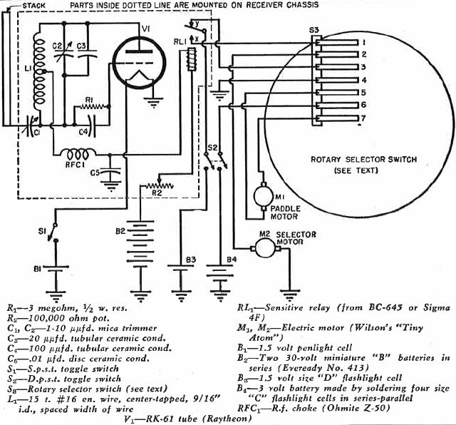
Fig. 6. Wiring diagram of the receiver, motors, and selector
switch contact fingers. The receiver is built on a small "U" chassis which may be
homemade and is mounted in the bow. S1 and S2 are mounted up on deck. See Figs. 7 and 8.
These motors are on sale at toy and model supply stores and are priced from $1.50
to $2.00 apiece. Despite a rating of only 1/2000 horsepower, one of these little
motors is capable of propelling a model boat at greater than scale speed.
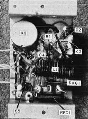 Fig. 7. Bottom view of the receiver.
The RK-61 tube, which has no socket, is mounted along the centerline of chassis.
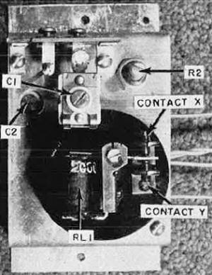
Fig. 8. Top view of the receiver. The relay shown is from a surplus BC-645 but
other types may be substituted (see text).
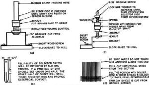
Fig. 9. (A) Selector switch shaft and bearing assembly, taken from an old Volume
control. (B) Adjustable brake for the rotary selector switch. (C) One of the contact
fingers. Length is approximate. (D) Faraday shield for the transmitter.
|
A similar motor drives the selector switch that controls both the direction of paddle
rotation and the rudder position. This motor, M2,
is mounted vertically in the stern (see Fig. 5). The rotating disc portion of the
selector is made from a piece of 1/4" plywood, 5" in diameter. It must be carefully
cut to shape and a groove filed in the edge to receive the rubber band that acts
as a drive belt. The shaft and bearing of the selector can be adapted from an old
Volume control. The control should be dismantled until all that remains is the shaft
and its associated panel bushing. This is then fastened to a U-shaped bracket cut
from sheet aluminum and the bracket is screwed to a small piece of wood previously
glued to the hull. Put a hole in the center of the selector disc with a 1/4" drill
and press the disc onto the old Volume control shaft. If the disc fits too loosely,
one or two applications of service cement to the edges of the hole will reduce its
size sufficiently to stop the disc from slipping on the shaft. A spacer bushing
keeps the disc at the proper height with respect to the switch motor's shaft.
Since a Volume control bearing operates smoothly, it is quite likely that the
selector disc may coast from one segment to another, thus going past a desired position.
This overshoot problem can be minimized by increasing the pressure of the contact
fingers against the disc or by constructing the brake shown in Fig. 9B. Tighten
the top nut on the brake only enough to keep the disc from coasting too far. Otherwise,
the selector motor will be overloaded and may, at times, lack sufficient power to
rotate the disc.
The segments of the selector disc can be fashioned from thin sheet metal. I used
heavy copper foil picked up at a surplus store. After the segments have been cut
to proper shape, fasten them to the disc with radio service cement. The contact
fingers for my switch were cut from the same copper as the segments. Use any metal
which is thin and fairly springy.
Rubber bands act as drive belts for both the paddles and the selector disc. No
pulleys are required on the motor shafts since the rubber bands are kept in alignment
by grooves in the edges of the selector disc and the paddle shaft pulley. The latter
item, by the way, was originally a part of the dial mechanism from an old radio.
A pulley cut out of 1/4" plywood should work just as well.
The paddle wheels are made from 3" discs of 1/4" plywood. Eight radial slots
3/4" long are cut in the discs at regular intervals as shown in Fig. 3A, and 1"
by 2 1/4" pieces of aluminum are forced into the slots. Cascophen or radio service
cement should be daubed on the ends of the paddles so that they will adhere to the
slots. The paddle shaft is made from two 1/4" carriage bolts, the heads of which
have been cut off, the two bolts then being fastened together with a 1/4" shaft
coupler. The paddle wheels have 1/4" holes drilled in the center and are held in
place on the threaded ends of the shaft bolts between nuts and washers. The shaft
bearings are simply 1/4" holes drilled in two aluminum brackets that support the
paddle assembly. The shaft is held in position between the bearings by means of
brass collars fastened to the shaft with set screws.
The rudder bearing, salvaged from another discarded Volume control, is mounted
on a small, L-shaped bracket at the rear of the hull. A piece of lightweight galvanized
iron is cut into the shape of a rudder and is soldered to what was originally the
potentiometer end of the shaft. An old dial pointer is fastened to the other end
of the shaft. The slotted arm, or "tiller," actuated by the rudder crank of the
selector switch is, in turn, soldered to the dial pointer (see Fig. 5). If no suitable
dial pointer is readily available you can, of course, cut out a small sheet-metal
tab, with a 14" hole for the rudder shaft, and go on from there. The slot in the
"tiller" is about 4 1/8" long. The crank arm is about 1 3/4''' between the center
of the selector shaft and the center of the screw-and-nut or whatever you use as
a drive pin or "handle." The dimensions of these three items are not critical. The
old Volume-control shaft will, of course, have to be long enough so that the crank
and swinging tiller will clear the top of the wood or plastic strip that holds the
selector fingers.
A superstructure must be built to hide the works of the model. The cabin and
pilot house are cut from lengths of 1/16" by 3" balsa wood, and then fastened together
with radio service cement (see Fig. 3). It is absolutely necessary that balsa be
used, otherwise the cabin will weigh too much and will make the boat top-heavy.
Balsa may be purchased in strip form at almost any store selling model airplane
supplies. It is easily worked, the only tool required being a sharp razor blade.
Both the hull and superstructure are finished with a good grade of white enamel.
The deck, cabin roof, and pilot house roof are painted gray. Doors and windows may
be drawn on heavy paper with India ink, cut out and then applied to the cabin with
rubber cement. A hole in the roof allows the cabin to be slipped down over the smoke
stack. The superstructure merely sits on the deck and may easily be removed for
making receiver adjustments.
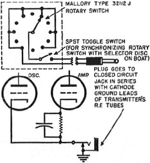 Fig. 10. Remote selector switch for use with
an 11-meter amateur transmitter. A key or toggle switch may be used instead.
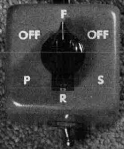
Fig. 11. The ham-rig switch of Fig. 10. It is turned counter clockwise
to control the receiver selector switch on the boat.
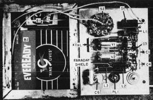
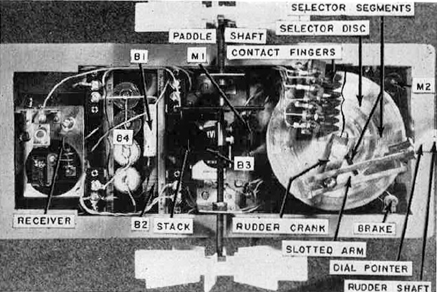
Fig. 12. All transmitter parts are mounted on one cover of a 3"x4"x5" utility
box. The tube sockets mount on L-shaped brackets. Holes should be drilled in the
case opposite C1, C4, and
C6 for adjustment alter the cover is fastened to the box.
|
Since the motors used in the "River King" are very small, it is important that little
power be wasted in friction. Make certain that all bearing surfaces are kept well
oiled. The fingers and segments of the selector switch, as well as the points of
the receiver relay must be kept very clean. Apply a little carbon tet to them at
regular intervals. Steer clear of any kind of contact dope, though, because it will
pick up dust and dirt, thus resulting in unreliable selector operation.
The Citizens Radio Service transmitter, designed as a companion for this receiver
(Fig. 13), will operate either on the Citizens Service frequency or in the amateur
band 26.960-27.230 mc., depending on the crystal used and your license privileges.
If you are already lucky enough to be the owner of an 11-meter amateur mobile transmitter,
you have little reason to build a whole new rig just for radio control purposes.
All you have to do is connect a switch in series with the ground leads to the cathodes
of the r.f. tubes as shown in Fig. 10. Although a telegraph key or toggle switch
might be used, a rotary switch is superior, because it gives a visual indication
of the various ship maneuvers. As long as the switch is not rotated too rapidly,
and in a counter clockwise direction, the selector disc on the boat and the switch
knob will stay in sync. Should the two get out of step for any reason, a toggle
switch in series with the rotary switch may be opened and the knob set to the position
corresponding to the maneuver being performed by the boat. Such a switch is shown
in the remote-control switch box, Figs. 10 and 11. It is not included in the self-powered
Citizens Band transmitter, because the transmitter can be turned off to reset the
selector switch and turned right on again, as the 3V4's require no warm-up time.
One precaution must be observed when adapting a mobile rig to radio control.
Be sure to key both the oscillator and the final. Otherwise there is a possibility
that some r.f. energy will be radiated, even though the final is off. The superregenerative
receiver is very sensitive and the slightest amount of r.f. leakage from the transmitter
will keep the relay from operating properly.
In those cases where no amateur mobile rig is available, it will be necessary
to construct a special radio control transmitter. For greatest convenience and portability,
dry battery operation is a "must." Since no great distances are to be covered, only
small power output is required. At first thought it might appear that a one tube
crystal oscillator would perform the job satisfactorily. However, there seems to
be no easy way to obtain adequate power from any of the common 1.4-volt filament
tubes when used as oscillators with 11-meter overtone crystals. Even the simplest
transmitter for 27 mc. appears to require a minimum of two tubes.
The first circuit I tried employed a crystal near 6800 kc., doubled in the oscillator
and also doubled in the final.
Usable output was obtained on 27 mc., and since a low frequency crystal is much
cheaper than one of the over-tone type, the circuit looked quite promising. That
is, until a check with an all-wave receiver revealed that the transmitter's output
in the vicinity of the twenty-meter amateur band was less than 30 db below the 27
mc. output. Consequently this particular circuit failed to meet the technical requirements
for Class C Citizens Radio Stations, which state that spurious emissions must be
at least 40 db down.
The transmitter finally evolved is diagrammed in Fig. 13. It uses a 3V4 as a
27 mc. overtone crystal oscillator and a 3V4 amplifier. Checks show that when the
27 mc. signal is 30 db over S9, the 54 mc. output is so low that it fails to move
the needle of an SX-71 receiver's "S" meter, thus easily meeting the FCC's requirements.
There are two main factors which hold the harmonic output to such a low level. The
amplifier is operated with only a little more than "Class A" bias, and a Faraday
shield (Fig. 9D) reduces capacity coupling between the final tank and the antenna
coil.
All transmitter parts are mounted on the front cover of a 3" by 4" by 5" metal
utility box, as shown in Fig. 12. Paint should be scraped from the inside of the
covers and from the edges of the box so that good electrical contact will be maintained.
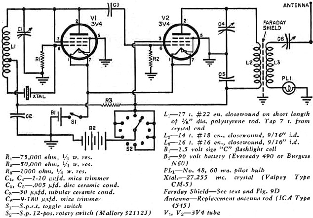
Fig. 13. Schematic of the Citizens Band transmitter. Switch S 2 turns the carrier on and
off. The receiver selector switch moves one position each time a carrier signal
is received. If the transmitter and receiver switches fall out of step, the transmitter
can be turned off and S2 reset to the boat's present maneuver.
The crystal fits into a miniature socket made by sawing in half the dual crystal
socket from a BC-746A tuning unit. Of course, any small FT-243-type socket may be
used, such as the Cinch-Jones #2 KM. unit. The tube sockets are fastened to the
panel with small L-shaped brackets.
A pilot bulb in series with the antenna coil gives an indication of output current.
It is merely pressed into a rubber grommet in the front panel. No socket is employed,
leads being soldered directly to the base of the bulb. The oscillator and amplifier
trimmer condensers are soldered to the panel. Two ceramic feedthrough insulators
support the 36" telescoping antenna, as shown in Fig. 2, the bottom insulator being
used to feed the transmitter's output via C6.
An Eveready 490 or Burgess N60 "B" battery will fit into the box and still leave
room for a single small flashlight cell to supply filament power. Regular snap-on
connectors are used with the "B" battery while a clip-type holder constructed from
pieces of aluminum makes for easy "A" battery replacement. The self-tapping screws
supplied with the 3" by 4" by 5" box should be removed from the back cover. Replace
them with short 6-32 machine screws and nuts. Otherwise, the sharp points of the
self tapping screws may work their way into the "B" battery and ruin it. A square
of corrugated cardboard used as a buffer between the rear of the transmitter and
the batteries will keep the latter from flopping around inside the box. Despite
its small size, the life of the "B" battery should be quite long because it furnishes
current only when a command is transmitted.
Adjustment of the transmitter is very simple. If you are a ham and plan to employ
the 11-meter amateur band, you can make use of the simple instructions which follow.
On the other hand, if you expect to operate the transmitter as a "Class C" Citizens
Radio Station, the adjustments will have to be made by someone holding a commercial
operator's license.
Preliminary tests are made with the front cover removed from the box so a temporary
jumper should be run from the cover to the box in order to complete the filament
circuit. A milliammeter is then hooked in series with the "B-plus" lead going to
the tap switch. Turn on the filaments, make sure the tap switch is on a live spot
and note the plate current. If it exceeds 25 ma., the chances are that the crystal
is not oscillating. Adjust C1 until a point is reached where the current
drops sharply, denoting crystal oscillation. C4
should be tuned from minimum to maximum capacity. Somewhere in this range, the milliammeter
will show a small dip, probably not more than a mil or so. Set C4 at
this point of minimum current.
Pull the antenna out to its full length and tune C6 for maximum brilliance
of the pilot bulb. When the transmitter is operating correctly, total plate current
will be in the neighborhood of 20 ma. and the bulb should glow brightly. Attach
the cover and, through holes drilled in the case, readjust C4 and C6
to maximum bulb brightness. C1 should then be tightened as much as possible.
However, if it is set too tightly, the crystal will oscillate erratically, on the
wrong frequency, or it may not start at all as the tap switch is rotated. Choose
a setting where the bulb lights just as soon as the tap switch hits a live contact.
Finally, the carrier frequency must be checked. If the unit is to work in the
11-meter amateur band all one has to do is make sure that the output appears somewhere
in that band. When the transmitter operates as a "Class C" Citizens Station, however,
a very critical frequency check must be made. The FCC requires that the carrier
be within .04% of 27.255 mc. According to my slide rule, this is a deviation of
not more than 10.9 kc. Actually, the transmitter should be much closer to the assigned
frequency in order to allow for temperature variations, etc. which can crop up in
normal use.
Although no operator's license is required for Citizens Band equipment, a Citizens
Radio Station license must be obtained by completing FCC Form 505 and mailing it
to the nearest Commission field office. Before filing Form 505, it will pay you
to read carefully Part 19 of the Commission's "Rules Governing the Citizens Radio
Service." You can obtain it from the Superintendent of Documents, Government Printing
Office, Washington 25, D. C. for ten cents in coin.
I've had a great deal of pleasure from the "River King. If you decide to build
and operate a similar model, you, too, can look forward to many hours of fun. And
don't overlook the fact that a Citizens Station may be operated by anyone, provided
he has permission from the licensee. Youngsters, especially, get a kick out of putting
the boat through its paces. Maybe you can go in partnership with your son or younger
brother - he to build the boat, you to wire the radio equipment. No matter how you
go about it, try a radio-controlled model. I know you'll find the effort worthwhile.
BIBLIOGRAPHY
North, William L.; "Radio Control of Model Boat," RADIO &
TELEVISION NEWS, August 1950.
Ford, Walter B.; "A Six Foot Radio-Controlled Model Boat," RADIO & TELEVISION
NEWS, July 1951.
McEntee, Howard G.; "Proportional Radio Control," RADIO & TELEVISION NEWS,
September 1951.
MacNabb, Vernon C.; "Radio Control on the Citizens Band," RADIO & TELEVISION
NEWS, March 1952.
Good, Walter A. & Good, William E.; "Receivers tor Radio-Controlled Models,"
QST, September 1951.
Lawson, Harry W., Jr.; "A Radio-Control System for Models," QST, February 1952.
Safford, Edward L., Jr.; "Model Control by Radio," Gernsback Library No. 43,
Radiocraft Publications, Inc., New York.
Posted June 1, 2013
|