|
Here is a nifty little project
for those of you who still actually build your models. Finding plans for a flight-proven
rubber band-powered helicopter is rare. This construction article and plans for
the Unicopter, a one-bladed chopper by Mr. Bill Hannan, appeared in the May 1973
edition of American Aircraft Modeler. It can be made out of a handful of
materials that are probably laying around your hobby bench area. It might not be
as exciting as a Blade MCX2
coaxial rotor RC helicopter, but... oh wait, it actually might just be as exciting
after all! Unicopter
 By Bill Hannan By Bill HannanHelicopters are among the
oldest of flying machines-at least in idea form. Leonardo da Vinci was doodling
designs for them back in the 15th century. Yet, even today, helicopters remain much
misunderstood, and only very recently have successful radio-control models of them
been developed.
Our miniature 'copter was designed to provide maximum fun for a mini-mum investment
in time and materials, but will still offer the chance to explore the problems associated
with rotating-wing aircraft.
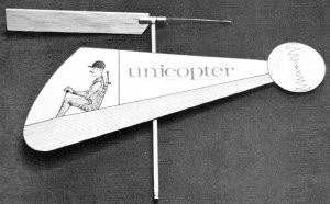
One blade rotor easily flies this rubber band-powered and paper
helicopter.
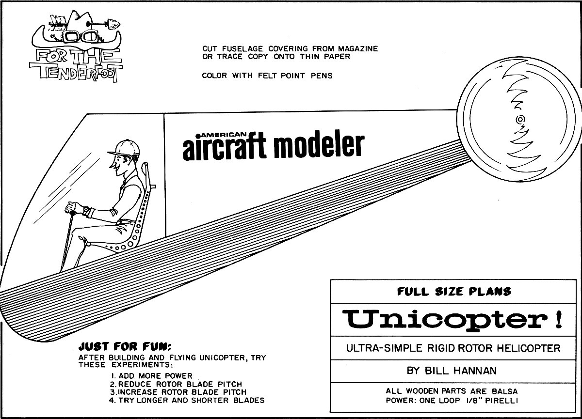
Back side can be decorated by copying the lines from the front
side to the back. Don't copy the words, they would only come out backwards!
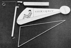
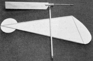
For a helicopter, what could be simpler? Body rotates a little
in flight.
CONSTRUCTION
Begin construction by building the triangular fuselage framework from fairly
hard 1/16" square balsa strips. A sheet of waxed paper will keep the sticks from
adhering to the plan while the glue is drying.
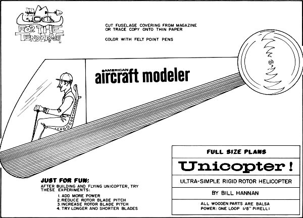
The fuselage covering may be cut directly from the magazine, or if you like to
preserve your AAMs, make a tracing of it on thin paper. Glue the triangular frame
to the back of the fuselage covering, and apply a few weights to hold the assembly
flat while it dries.
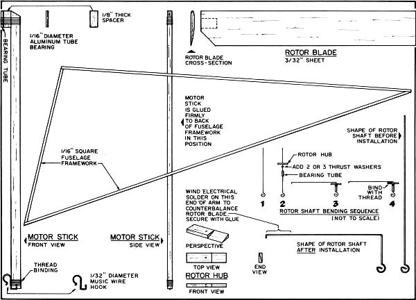
Next, cut the motor stick to length from a strip of 1/4 x 1/8" balsa of medium
weight. Cut the angle on the top end, and glue on the little bearing spacer piece,
which may be cut to size from leftover motor stick stock.
Bend the lower motor hook to shape from 1/32" dia. music wire and bind in place
with sewing thread and glue. The rotor shaft bearing is cut from a length of 1/16"
OD aluminum tubing by rolling a single-edge razor blade over it. Snap the tubing
along the scored line, and sandpaper or file off any rough edges. The bearing is
secured to the motor stick with thread and glue.
The completed motor stick may next be glued to the fuselage framework in the
position shown on the plans.
The rotor is cut to size from a piece of medium-hard 3/32" sheet balsa. Sand
it to an airfoil shape with a sanding block. A general cross-section is shown on
the drawing, but the exact shape does not seem to be critical.
The rotor hub is made from a hard piece of 3/32" sheet. Carefully cut away one
corner to accept the rotor blade. Drill a hole in the hub center for the rotor shaft,
being careful that it is "square" with the face of the hub, so that it will run
true.
A length of 1/32" dia. music wire is used for the rotor shaft. First, bend the
hook end to shape. Next, slide the shaft through the rotor shaft bearing, add a
couple of brass thrust washers, and the rotor hub. Using the drawing as a guide,
make the right-angle bend in the shaft above the rotor hub, and also at the extreme
end of the wire. This small bend serves to help retain the rotor balance weight.
Using sewing thread and glue, bind the shaft arm to the rotor hub.
The rotor may now be glued onto the hub. Obtain a length of electrical solder,
and wind it neatly onto the balance end of the rotor shaft. Hold the motor stick
horizontally, and you will be able to determine the static balance by trial and
error. A thin coat of glue will keep the solder in place.
And there you have it! Power on our model was provided by a single loop (two
strands) of 1/8" flat Pirelli rubber. With limited winds, the model may be flown
indoors. With more power, the Unicopter can reach surprising altitude outside. After
winding, release the rotor a moment before letting go of the lower motor stick.
In some cases, stability may be improved by adding a small amount of solder or clay
to the bottom of the motor stick. For maximum per-formance, lube the rubber and
stretch wind with a mechanical winder.
Once you have constructed and flown the basic Unicopter, you may wish to try
a few experiments. For example, in theory, the rotor counter-balance arm should
be bent slightly downward and forward to provide better dynamic balance. Then too,
the addition or subtraction of weight in small amounts may contribute to reduced
vibration. This is easy to test by holding the model loosely by the base of the
motor stick, where vibration effects can be both seen and felt.
You might also care to experiment with different rotor lengths, areas and thicknesses.
Additionally, different sizes of rubber motors may be tried. A great deal can be
learned very quickly in this manner, which could prove useful on more sophisticated
model helicopters. Happy hovering!
Unicopter Plans - Sheet 1
Unicopter Plans - Sheet 2
Posted May 7, 2022
(updated from original post on 10/22/2011)
|