|
While admittedly a bit outdated, these troubleshooting
tips for R/C airplane problems are useful for teaching problem identification and repair techniques.
Even though most radio controlled model airplanes are purchased ready to fly (RTF) these days, they
do manage to crash and need repair or parts get worn out and need repair. Many RTFs are barely airworthy
out of the box and a little time spent optimizing the setup before the first flight will pay off in
much longer life and enjoyment of the model. Radio Control Fans' Most Popular Sport: Bug Hunting
By Howard G. McEntee
A little over a year ago ATH expounded upon the fine art of "bug" hunting - especially
as it applied to R/C bugs. The hunt still goes on, and always will as long as we operate R/C. That being
the case, let's look at some more of these little devils that have come to light since our last session
at this national R/C pastime. Some bugs, of course, are the result of poor - or no maintenance,
while others just appear even though you are a most careful operator. We have come to the conclusion
that the R/C "experts" are simply those flyers or boatmen who have profited most by every bug hunt;
they remember each and every encounter, and conduct their operations so that the old bugs, at least,
will not be encountered again. Well, let's go on with the hunt, taking up first.
Installation Bugs 1. Many modelers use the flat type of battery case to hold
pen cells for filament and escapement power. The cases have lugs at each end of each cell for connection
purposes, and in the small sizes the lugs are long enough so that by twisting them sideways they can
be soldered directly to each other, thus eliminating the need for wire connections. Looks like a neat
way to make these connections but - don't do it! When connections between adjacent cells are made this
way, it takes a lot of the spring out of the battery case ends; it is entirely possible for one cell
to have good contact, while contact to those on each side may be poor or even non-existent. If the cells
are in parallel, one of them may be doing all the work, while in series connections you could have a
variable or open circuit. Leave the lugs upright as they come, and make connections between them with
flexible wire. 2. A proportional installation that had given good results started to act up;
when the engine was run at high speed, the rudder tended to pull to one side and stay there. Looked
like relay vibration. Fortunately the effect could be studied when the plane was held in the hand with
engine running; as engine speed was increased, rudder would pull farther and farther to right, but at
low or moderate speeds all was well. 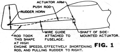
Then it was discovered that the rudder would pull to the same side with the receiver
turned off, with the actuator circuit open, and finally with all batteries out of the plane! The rudder
was operated by a metal push-pull rod of ample diameter; however, as engine speed increased, this rod
could be seen through the clear doped fabric side of the fuselage to take on a shape like a stretched
out letter "S"; as seen in Fig. 1, the guide at the center had no damping effect on this vibration,
since it was at a "null" point. As the vibration amplitude increased, the rod was effectively
shortened, pulling the rudder to the right. This vibration was effectively squelched by using a wooden
pushrod with music wire ends; a torque-rod linkage would probably not give as much trouble from this
sort of vibration, though the shortening effect might tend to make the rod bind in its bearings.
3. When bending metal for battery contacts and other purposes, note that the material has a definite
grain, and will bend without cracking much better in one direction of the sheet than in the other. This
is especially true of partially hardened metals such as shim brass. Bend a test strip to see which is
the best direction, then make your bends with as large a radius as possible. Better still, lay things
out so that no bends at all are required.
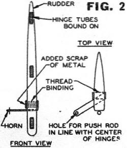
4. Looseness shows up in rudder linkages in queer places. In one case where the
plane seemed to have a rather indefinite neutral adjustment, it was found that the rudder horn (used
with a push-pull rod) had loosened slightly, allowing the rudder to move a quarter of an inch back and,
forth, with the horn held in fixed position. The horn had been well cemented originally, but the joint
had been loosened in handling; it was re-cemented and the joint secured firmly with thread applied with
a heavy needle as in Fig. 2.
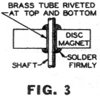 5. Another case of wandering neutral (in a proportional ship this
time) was traced to the disc magnet of the actuator becoming slightly loose on the shaft; when the magnet
was held firm, the shaft could be turned enough to move the rudder back and forth a quarter inch or
so. Soldering to these magnets is something of a problem, since the magnetic material is of a type that
doesn't take solder too readily. It's best to use good strong acid flux (clean the joint carefully after
it is made); another good trick is to put a piece of brass tubing through the hole in the magnet - in
those cases where the magnet has no center of soft metal - "rivet" the tubing over on top and bottom,
then put the shaft through the brass tube and solder the whole works together. See Fig. 3. 5. Another case of wandering neutral (in a proportional ship this
time) was traced to the disc magnet of the actuator becoming slightly loose on the shaft; when the magnet
was held firm, the shaft could be turned enough to move the rudder back and forth a quarter inch or
so. Soldering to these magnets is something of a problem, since the magnetic material is of a type that
doesn't take solder too readily. It's best to use good strong acid flux (clean the joint carefully after
it is made); another good trick is to put a piece of brass tubing through the hole in the magnet - in
those cases where the magnet has no center of soft metal - "rivet" the tubing over on top and bottom,
then put the shaft through the brass tube and solder the whole works together. See Fig. 3.
6. A queer bug showed up on a proportional plane, which, when being checked just before launching,
showed that the rudder was working fine - but just the opposite to the direction the control switch
was being moved. Frantic checking failed to reveal the cause, and since everything seemed to work O.K.,
the plane was flown by turning the control box over. A more painstaking check in the peaceful
atmosphere of the shop revealed the trouble; in correcting the loose magnet mentioned in Item 5, the
actuator had been reassembled with the disc turned around 180 degrees from its proper position. After
the repair was finished, tests of the job were made by simply operating the receiver relay by hand,
and it wasn't until the system had been set up to fly that the reverse rudder action had been noticed.
Moral - mark the magnet with colored dope so you can always tell the proper position (such a
mark also enables you to tell at a glance if the magnet or control arm has come loose on the actuator
shaft). 7. Note to beginners. When the relay is mounted separately from the receiver, it is
the relay that should be shock-mounted; the receiver may be nested quite firmly in sponge rubber, more
as a matter of protection against damage than as shock or vibration protection. Incidentally, if you
have an obscure vibration problem in your plane that shows up only when it is in flight with the engine
running, there are a couple of good ways to run it down. Often such trouble will not show up with the
plane sitting on the ground, or even when it is held in the hand with the engine running. Try suspending
it by several loops of rubber running under the wing near the tips; this will let the plane shake like
it does in free flight. Even this often does not let you run down the trouble, but there is
still another way and one you can apply indoors, at that. Hold one of the vibrating or oscillating sanding
machines against the fuselage (with a piece of sponge rubber between the vibrating plate and the fuselage
to prevent damage to the covering). This will shake the plane almost as much as a prop with one blade
busted off! You can govern the degree of shake by the amount of pressure you use; turn the sander in
different directions to make sure you vibrate the fuselage in the same direction that engine vibration
occurs. Receiver Bugs 1. If you have a stubborn case of vibration affecting
the receiver relay. and can't seem to cure it any other way, you might consider using another receiver
circuit! Not as drastic as it might sound, for this reason: some receivers operate at low plate current
when there is no signal, others idle at high plate current. The former will give better operation in
a vibrating plane (when used with an escapement) since the relay contact you utilize is the one that
closes when the armature pulls toward the magnet - this contact normally has much greater contact pressure
than the opposite contact, which is held closed only by light spring tension. 2. It has been
suggested that relay contacts be cleaned periodically with a piece of paper drawn between them. On some
relays, though, this operation must be done with care, for it is possible to throw the relay out of
adjustment. For example, on the popular Neomatic relay (the type that has a flat strip spring) the spring
has an indentation into which the adjustment screw fits. This end of the spring is right back of the
contacts, and if paper is pulled through the points carelessly, the indentation can be forced off the
tip of the screw; this will increase relay operating current quite a bit - enough in some cases to render
the receiver inoperative. 3. It has been found advisable to resolder the connections between
mounting eyelets, lugs or rivets that carry current, and printed circuit base plates, in receivers using
this type of construction. This is especially important where such parts are used to support the receiver,
for vibration apparently breaks the original solder joints, and they are also heavily strained in crashes
and hard landings. We have not heard of this trouble in printed-circuit transmitters, which of course
don't take such a beating.
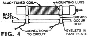
4. When the receiver tuning inductance is supported by its own lugs, as is often
the case with slug-tuned coils, it has been found that the lugs can break as in Fig. 4. When this
happens, the break is usually not visible to the eye unless the coil is lifted up at one end or the
other. Re-solder job on such a broken lug is not too reliable; best idea is to replace it with a new
one - preferably of heavier metal - or add some sort of physical support to the coil form.
Transmitter Bugs 1. Builders have been advised to use a pilot lamp to tune
up a new transmitter - a very good idea. But after the. unit has been checked out, the bulb should be
removed and replaced by the regular antenna; when this is done, the transmitter will have to be completely
retuned. Leave the bulb out of the circuit when the transmitter is set up in the field, unless the instructions
definitely say that it should be lighted when the equipment is in use - as in Babcock and Good transmitters.
You can utilize the bulb to load the transmitter, when working in the shop; this cuts the power output
down a lot, so that the nearby receiver won't be overloaded. Another point - don't tune up a
crystal-controlled transmitter without some sort of output load (either a bulb or the proper antenna)
connected, as you may damage tubes or crystal.
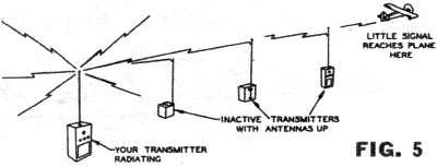
2. On a busy flying field, a most imposing lineup of transmitting antennas may often be seen. If
you are at one end of the line, it is smart not to let your plane fly down the other way, as in Fig. 5,
so that the line of antennas is between plane receiver and transmitter; ships have been spun in this
way, for the intervening antennas can soak up enough of your signal so that practically none gets to
the plane. 3. It is possible to tune up a transmitter so that it puts out a good signal, but
not on the crystal frequency: this usually occurs when the tuning condenser is near the low capacity
(higher frequency) side, and when operating this way the crystal has no control of the signal, which
will be very unstable. A field-strength meter will quickly show up the mistuning. There is another ailment
to watch out for, and this one is due strictly to a defective crystal; crystals have been known to oscillate
strongly on two different frequencies, and they will jump from one frequency to the other as the tuning
knob is rotated: Such crystals can also put out a strong second harmonic signal on the "wrong" frequency;
one 27 1/4 mc crystal we checked gave good output at 52 mc, but when tuned to the proper point, would
oscillate smoothly on 27 1/4 mc. The point of all this is that there is no guarantee that you
are on the correct frequency, even though you have a good crystal in your transmitter; the outfit has
to be tuned up properly - and a reliable field strength meter is fine insurance to make certain it is.
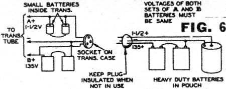
4. Hand-held transmitters are rightfully popular, but modelers who like to make long flights have
to watch their batteries most carefully. Larger batteries can be put in a case on the ground, but that
nullifies the mobility that is one of the best selling points of the hand-held unit. You can put the
extra batteries in a pouch slung over your shoulder, with connections made via a plug and socket to
the transmitter. The latter will work about the same with or without the extra batteries in use. If
you use a Beep-Box or proportional pulser, the knapsack set of batteries will insure long reliable life
with the extra current drain, See Fig. 6. 5. Dropping B voltage cannot do much harm to
the transmitter - it just means less output. But low A voltage can damage the tubes, especially if you
are running at fairly heavy plate current. The tube filaments will not be heated hot enough to handle
the plate current; tubes "strained" this way often won't work properly even after the low A batteries
have been replaced. Well, there we have the of bugs; there are many more, of course -
new ones are chased down at almost every flying session. Do you readers find these bug hunts worthwhile
and want see them continued?
Posted October 14, 2013
|