|
New airfoils today are designed by computer - literally. As with
circuit and mechanical simulator software, aerodynamic fluid flow
algorithms exist that will run thousands of iterations on an initial
design until it reaches the goal set by the engineer. Limits are
defined on parameters such as chord, wingspan, airspeed, thickness,
manufacturing tolerances, temperature coefficients, material stiffness,
to name a few, and then a mouse click sends the computer into its
happy place while obeying convergence rules and arriving (hopefully)
at a solution that provides the performance characteristics desired.
If it fails to produce the expected result, a new set of starting
points, limits, and convergence algorithms can be stipulated and
then the process is run again. The engineer can focus his attention
of other pressing matters (like drinking a cup of coffee) while
the computer does his bidding.
Prior to the computer age, airfoils were designed according to
a set of rules empirically determined through wind tunnel testing
of many varieties of shapes. The original work was performed by
the National Advisory Committee for Aeronautics (NACA)
- forerunner to today's NASA. Volumes were published on airfoils
meant for particular applications - speed, heavy lifting, short
field operations, high altitude, etc. Nowadays rather than thumbing
through a tome that takes two men to lift, you simple click on a
pull-down menu and there you go.
Ritz on Airfoils
One of modeldom's best known designers has distilled all current
state-of-the-art data on wing sec-tions down into a single you-read-it-at-a-glance
chart
By Gerald "Jerry" Ritz
A common question is "How do you go about choosing the best airfoil
for a projected model design?" The answer to this is that there
is no single best airfoil for a model except in calm air with no
turbulence to produce variations.
Max Hacklinger of Germany, one of the world's keenest minds on
airfoil design, had this proven to him decisively at the Nordic
World Championships on two occasions, when with undoubtedly the
best model for pure glide duration, he wasn't able to squeeze by
the downdraft air factor to which high performance models are especially
susceptible. He has since then switched to indoor models where his
scientific skill will not be subjected so much to the vagaries of
the air.
Of course, we can choose the best general area of airfoils for
any given design, with a refinement of choice for given weather
conditions. To do this we have to make an analysis of the design
factors of airfoil sections.
One of the best all-around methods for describing the physical
characteristics of airfoil sections for use in model aircraft is
undoubtedly the 4 digit system as originated by the N.A.C.A. Here
is stated the essential proportion of height of mean camber, with
its positioning, and the maximum overall thickness of the section.
One of the factors not found in this 4 digit system is the data
on body form, inasmuch as the NACA used standardized thickness forms
in most of their early sections. (Of course, on specialized high
performance sections such as some of my glider sections and some
of Benedek's top performance sections, it is necessary to depart
from these standardized body forms.)
Now in a further analysis of this 4 digit system (which actually
consists of 3 descriptive features: 1st number - Height of mean
camber in percent of chord; 2nd number - positioning of this mean
camber high point in tenths of the chord from the leading edge;
3rd and 4th numbers - maximum thickness of the section in percentage
of chord) we find that each descriptive feature has a definite relationship
to the type of model on which the section is to be used. To illustrate
the various general areas into which different types of models will
fall, we have laid out a chart diagramming the two basic airfoil
features - the height of the mean camber, (6409) and the chordwise
high point of this camber, (6409). In this example, the first number,
6 means that the airfoil mean camber height is 6% of the airfoil
chord length. The second number, 4, means that the maximum high
point of this mean camber is located at 40% of the chord from the
front of the airfoil.
For example, in a speed model or in a plane designed for aerobatics
such as a radio control contest job, very little height of mean
camber would be used. The reason here is that in these cases the
wing is used mainly for neutral suspension of the model, and for
purposes of control, and very little positive lift (which is a feature
of camber) is required. Because of this, the camber for this type
of model will range from 0% for use with high speed jobs, to a high
of about 3% in slower flying scale R/C jobs.
In engine powered free flight models, however - the object being
duration - we must necessarily use some camber to obtain enough
lift for a good glide. However, the amount of camber we can use
is limited by the fact that the power phase of the flight is at
quite high speed and too much camber would create too much lift
and be hard to control, and also it would create too much drag,
which would slow down the speed thereby reducing the climb which
is so necessary for good duration. Therefore in this case we use
moderate cambers, with a low of about 3% to a high of about 6%.
Hand launched gliders, with their high powered launch phase, fall
into this same category.
In outdoor rubber powered models, where the power surge is not
so great, it is possible to move toward the higher lift sections
characterized by the higher cambers, both for good lift in the power
phase, and principally for better gliding performance. In this type
model the mean camber should range between a 4% low up to a high
of about 7%.
The final outdoor category of pure glide is used mainly by towline
gliders, where the model is towed to maximum height without any
regard for camber or its effect in the tow, and then cast off to
glide. Here we come into one of the highest ranges of mean camber
of any type of model. In this region of pure glide, the most effective
mean camber for duration will fall into the low of 5% up to a maximum
of about 9%.
One factor that will modify the height of the mean camber on
free flight models is that in very windy turbulent weather, the
highly cambered airfoils tend to stall easier. So if a model is
being designed for windy weather, use the lower range of cambers
for greater consistency. For calm weather flying, use the higher
range of cambers for maximum duration.
Now we come to an argumentative phase, which concerns the mean
camber for indoor duration models. Because of the low power surge
of this type of model, where the power flight contains nearly the
whole of the duration pattern, the flight falls into much the same
category as pure glide, except for there being just enough power
added on the average to about maintain altitude. Although some of
the experts have been using lower cambers (down to even 3 or 4%)
for maximum duration on indoor rubber powered models, our figures
show that the camber height should be from a low of about 5% up
to a maximum of about 9%. Following the reasoning as outlined above,
I would venture a prediction that the first man in the "one-hour"
club will use an airfoil camber of about 8%.
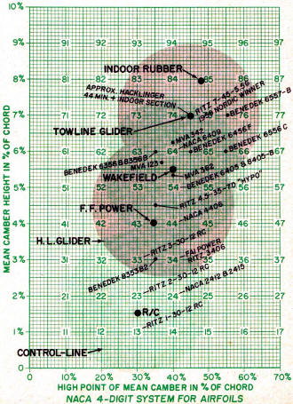
NACA 4-Digit System for Airfoils
So far we have discussed only the height of the mean camber.
And very frankly, this is by far the most important criteria of
the three digits. Next in order is the chordwise placement of the
high point of the mean camber. If you will examine the chart, you
will see that the lower cambers used in models generally have the
high point quite well forward in the chord, and as the camber height
increases, the high point gradually moves rearward. There are good
reasons for this. As the camber increases, it is a pretty sure bet
that the Reynolds Number (principally a factor of chord length x
speed) is decreasing - that is, the airfoil is being used on a slower
flying model. This generally means a thinner airfoil to get more
undercamber, as tests have shown that the undercamber of an airfoil
carries a gradually increasing proportion of the load at lowering
Reynolds Numbers. With this increased undercamber, care has to be
taken not to allow too high an undercamber entry angle, or there
will be a stagnant area with loss of lift and increase of drag.
To help avoid this, the high point of the undercamber can be moved
rearward. This automatically shifts the mean camber maximum high
point rearward also. In conjunction with this, the higher trailing
edge undercamber angle of a rearward location of maximum mean camber
will produce considerable additional lift without too much drag.
Care must be taken not to overdo this, however, as lift produced
by trailing edge deflection builds up quite fast, and in this critical
Reynolds Number region, can produce a stalled condition rather easily
in turbulent air.
Therefore we can draw the following conclusions: When choosing
an airfoil for use on a model for turbulent air, do not use too
much camber, and keep the high point of the mean camber fairly well
forward - (lower left hand area of the circle). For calm air flying,
however, use the higher cambers, with the camber high point more
rearward (top right hand area of the circle).
An interesting observation is that the camber of Hacklinger's 44·
minute indoor model and the mean camber on my "Continental" Nordic
glider were nearly identical.
The large X in each circle is a suggested ideal choice of camber
for average weather for the type of model portrayed by that circle.
The third factor of the NACA digits is the maximum thickness
of the section measured in percent of the chord. Here we have two
prime considerations. One is the matter of structural strength,
and, of course, the thicker the airfoil, the greater the strength
that can be built into it. The other factor is the matter of efficiency,
where in these low Reynolds number regions the thin sections have
a higher L/D ratio than the thick sections. Here again the weather
factor enters into the problem. The thicker sections are more tolerant
of rough weather conditions. They have a more gentle stall, and
their center of pressure shift is generally much less violent, mainly
because of the greater movement of the air separation point on the
round nose of the thicker sections. Thus they are easier to control
in turbulent air.
However, this very roundness of the nose of the airfoil that
makes control less difficult in turbulent air, is a decided disadvantage
in calm air, especially in the lower Reynolds number region. Here
we count to a large extent on the small radius nose to help provide
enough natural air turbulence over the airfoil to prevent the early
breakaway with high drag so attendant to airfoils flown at low Reynolds
number in a lifting condition.
In R/C contest models, where the Reynolds number is fairly high,
one of the main differences between a thick or thin section is that,
as stated before, the round nose of a thicker section will be more
tolerant to control than a sharper nosed section, and the section
will have more drag and "grip" on the air, thus allowing patterns
to be flown more slowly.
So if you are a beginner in R/C by all means use a thicker section
with a round nose to get a smooth, more sluggish control that you
can keep up with. However, a real expert with a good control unit,
who can handle high-speed maneuvers, can get sharp and decisive
patterns with a thinner, sharper nosed section at speeds a beginner
could not hope to handle. In years ahead, look to the time limit
in R/C to become increasingly important as a judging factor in contest
flying. I would suggest points be given for total time saved in
flying the prescribed patterns.
As we enter the free flight range, with the duration factor to
contend with, we are immediately forced into the thinner type sections
for purposes of efficiency. In free flight power, for example, a
10% thickness of section would be about the maximum anyone would
go to, and many of the high performance jobs, especially in the
FAI classes, are down to about 6% thickness. In Wakefield models
and Nordic gliders, the thickness is down even more in many of the
best models.
By this time you can see the general trend: As the Reynolds number
the airfoil is flown at is decreased; the overall section thickness
is decreased also. The limiting factor in most cases of outdoor
models is either structural or that oft-repeated turbulent air problem
where a thin section coupled with high camber may not give you the
necessary consistency for contest flying.
The final phase of the thickness category is, of course, the
indoor duration models, with the lowest Reynolds numbers of all,
and appropriately the thinnest sections of all ... and here where
we don't have to worry unduly about turbulent air. We can freely
go to the thinnest of sections and the greatest cambers for maximum
efficiency, and naturally have the greatest duration potential of
any type of model.
The next time you design or build a model, keep in mind the three
criteria of the NACA digit system, and pick your airfoil carefully
for the type of model you have in mind, and for the conditions you
intend to fly it in, and it won't be long until you'll be giving
some of the experts a real "run for the money".
Posted June 13, 015
|