 Table
of Contents] Table
of Contents]People
old and young enjoy waxing nostalgic about and learning some of the history
of early electronics. Popular Electronics was published from October 1954 through April 1985. All copyrights (if any) are
hereby acknowledged.
See Popular Electronics articles
on aircraft modeling. See all articles from
Popular Electronics. |
I purchased a couple batched of vintage Popular
Electronics magazines off of eBay for use on my engineering website, RF Cafe; however, upon scanning through the pages I was pleasantly surprised to
find that many articles on radio controlled airplanes were included. The 1950s and 1960s were relatively
early in the R/C sport, and such things were still considered a novelty.
This article is from the December 1954 edition of Popular Electronics, written by E. J. Lorentz about
his transmitter design. It used a single 3A4 vacuum tube. As was the technique of the day, point-to-point
wiring was used in the chassis; printed circuits boards were yet to become ubiquitous. Of course all
the components are leaded, since surface mount packages did not become common place until the late 1980s.
The good thing about those methods is that just about anyone with a soldering iron could build the circuits.
Have you ever tried attaching an 0602 SM resistor to a PCB?
The Lorenz Transmitter
by E. Z. Lorenz
 The transmitter to be described, which is operated on the license-free
frequency of 27.255 megacycles, enables the operator to send out a signal which remotely con-trols model
planes, boats, cars, or other mechanical units. It is designed to be used with the receiver (The Lorenz
"Sixty-One") presented last month. The only FCC regulation on operating this, or any other crystal-controlled
transmitter in the Citizens band, is that an FCC form 505 be filled out and sent to the nearest FCC
of-fice. (Check with your local post office for the nearest FCC office.) The transmitter to be described, which is operated on the license-free
frequency of 27.255 megacycles, enables the operator to send out a signal which remotely con-trols model
planes, boats, cars, or other mechanical units. It is designed to be used with the receiver (The Lorenz
"Sixty-One") presented last month. The only FCC regulation on operating this, or any other crystal-controlled
transmitter in the Citizens band, is that an FCC form 505 be filled out and sent to the nearest FCC
of-fice. (Check with your local post office for the nearest FCC office.)
The Citizens bands include 27.255 mc. and 465 mc. The only type of transmitter which the radio-control
fan may build, if he is not a "ham," is one whereby the frequency is crystal controlled. Since this
is rather difficult on the 465-mc. band, we must be content to do our building in the 27-mc. band.
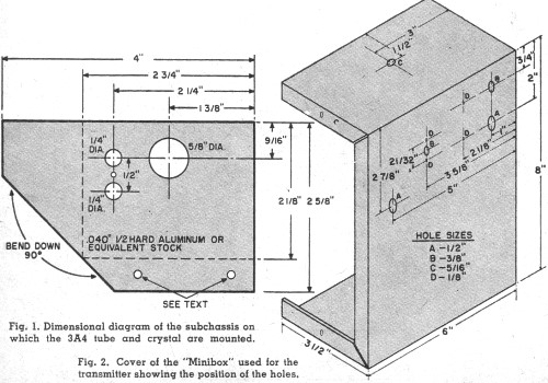
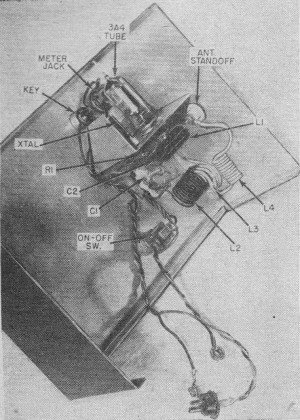
 Read this construction article carefully, and study the diagram
and photographs before starting work. First of all, the chassis should be cut, drilled, and bent from
.040-inch, 1/2 hard aluminum, or equivalent, as in Fig. 1. Next, the case, which is a 3-1/2" x 6" x
8" "Minibox," has its cover drilled according to Fig. 2. The chassis holes on the bottom flange, shown
in Fig. 1, should be drilled after the front cover holes are drilled. Hold the chassis against the cover
and mark holes on the flange as per front cover holes. Mount the tube and crystal socket on the chassis
before bolting the chassis to the cover with 4-40 3/8" machine screws. Read this construction article carefully, and study the diagram
and photographs before starting work. First of all, the chassis should be cut, drilled, and bent from
.040-inch, 1/2 hard aluminum, or equivalent, as in Fig. 1. Next, the case, which is a 3-1/2" x 6" x
8" "Minibox," has its cover drilled according to Fig. 2. The chassis holes on the bottom flange, shown
in Fig. 1, should be drilled after the front cover holes are drilled. Hold the chassis against the cover
and mark holes on the flange as per front cover holes. Mount the tube and crystal socket on the chassis
before bolting the chassis to the cover with 4-40 3/8" machine screws.
Mount the antenna feedthrough, the 35- μμfd. variable capacitor, the "on-off" switch, meter jack,
and keying switch as shown.
Wind coil L1 (see Fig. 3) according to the parts list, leaving leads about 1/2" long. Be sure the
winding is tight and the turns fit tightly against each other. After remov-ing the coil from the form,
give it a coat of clear nail polish. Wind the tank coil, L2, as specified in the parts list, leaving
the leads about 3/8" long. Space the turns evenly, after winding, until the length of the coil is 1".
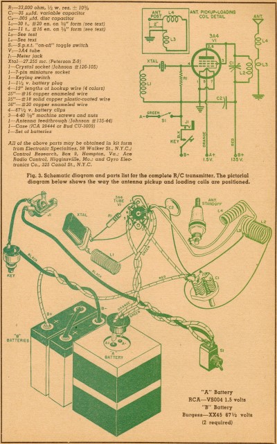 The antenna and loading coils, L3 and L4 are made from a 24" length
of #18 solid plastic-coated wire. Leave 1-1/4 to 1-1/2 inches between the two windings. L3 consists
of 3 turns wound on a 3/8" diameter form; L4 is 10 turns close-wound on a 3/8" diameter form. The antenna and loading coils, L3 and L4 are made from a 24" length
of #18 solid plastic-coated wire. Leave 1-1/4 to 1-1/2 inches between the two windings. L3 consists
of 3 turns wound on a 3/8" diameter form; L4 is 10 turns close-wound on a 3/8" diameter form.
We are now ready for final assembly. Follow the schematic in Fig. 4. Although not imperative, it
is desirable to have four color-coded wires for hookup. The colors used are: black for "B-," red for
"B+,"· green for "A-," and orange for "A+." About 15" of each are used.
Solder the "A+" filament wire to pin 5 of the socket. (Remember that all socket connections refer
to the underside of the socket.) The "A-" wire is soldered to pins 1 and 7 and also to the center eyelet
of the socket. Twist the "A+" and "A-" wires together for about 3 inches, cut the "A-" lead and solder
it to one side of the single-pole, single-throw switch. The other piece of "A-" lead is soldered to
the other side of the switch. Now twist the "A-" and "A+" leads together again for about 6 to 7 inches,
then cut, and solder to the "A" battery plug. The large pin on the plug goes to "A+." Place the tube
in the socket and check to see that the filaments light when the switch is turned on.
Solder coil L1 between the ground point at pins 1 and 7 and the outside crystal socket terminal.
Resistor R1 is soldered between pins 1 and 7 on the tube socket and the inside crystal terminal. Extend
the resistor lead from the crystal socket to pin 4 of the tube socket and solder. The .005-μfd. plate
bypass capacitor, C2, is sol-dered between the ground point and the rotor (movable plates) terminal
of the 35- μμfd. variable capacitor, C1.
Solder the tank coil, L2, between the rotor and stator (fixed plates) terminals of the 35-μμfd. variable
capacitor. Solder a short piece of wire between the stator end of the coil and pins 2 and 3 of the tube
socket.
 This completes the basic oscillator. Before starting the final hookup,
be sure the meter jack is insulated, by means of insulated washers, from the case cover. Use a short
piece of black wire to connect one of the sleeve terminals of the jack to one side of the keying switch.
Connect the two jack sleeve terminals together. Another short length of black wire is soldered between
the other jack terminal and the "on" side of the "on-off" switch. The "B-" black lead is soldered to
the remaining terminal of the keying switch. This completes the basic oscillator. Before starting the final hookup,
be sure the meter jack is insulated, by means of insulated washers, from the case cover. Use a short
piece of black wire to connect one of the sleeve terminals of the jack to one side of the keying switch.
Connect the two jack sleeve terminals together. Another short length of black wire is soldered between
the other jack terminal and the "on" side of the "on-off" switch. The "B-" black lead is soldered to
the remaining terminal of the keying switch.
A 6- to 8-inch length of red wire is soldered to the junction of the tank coil, L2, and the .005
μμfd. capacitor. Twist the black and red leads together, cut, and attach battery clips.
Now insert the tube and crystal in their respective sockets and attach a 0-25 or 0-50 milliampere
d.c. meter to a meter-jack plug and insert in the meter jack. Be sure the polarity is correct-the plus
terminal of the meter going to the side of the jack connected to the "on-off" switch.
To tune the transmitter, turn the switch on and set the variable capacitor to minimum, or until the
plates are unmeshed. Depressing the key will give a current reading of 25 milliamperes or more. Rotate
the variable capacitor until the current drops sharply to about 5 to 6 milliamperes. This indicates
that the oscillator is functioning properly. Failure to obtain a current drop indicates an incomplete
connection or a short to ground through the meter jack.
Next, install the antenna coil by inserting the three turns of L3 between the turns of L2 near the
plate end of the coil. Insert L3 only about two-thirds of the way into the tank coil. The free end of
L3 is sol-dered to the ground connection of the tube socket, and the free end of L4 is soldered to the
antenna post lug. Upon depressing the key, the variable capacitor will have to be readjusted to give
a minimum reading, which will, be about 2 milliamperes more than that obtained with the coils not in
place. After the minimum reading is obtained, set the variable capacitor to obtain a current rise of
about 1 to 2 milliamperes. For bench testing, your transmitter will now operate the receiver in last
month's issue of POPULAR ELECTRONICS.
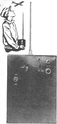
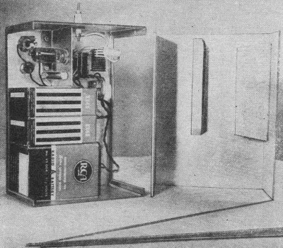 Note the two wood blocks screwed onto the bottom portion of the
"Minibox" as seen in the photo on page 53. These blocks serve to hold the "A" and "B" batteries in place
and should be added to the transmitter case after it has been completely assembled. Use a grade of soft
wood for this purpose. The center strip is about five inches long and one inch wide. It is so placed
as to press down on the batteries and hold them in place. The other block is also about five inches
long but is 2-1/4 inches wide. This screws onto the side of the case and hits up against the end of
the batteries keeping them from sliding across the transmitter. Note the two wood blocks screwed onto the bottom portion of the
"Minibox" as seen in the photo on page 53. These blocks serve to hold the "A" and "B" batteries in place
and should be added to the transmitter case after it has been completely assembled. Use a grade of soft
wood for this purpose. The center strip is about five inches long and one inch wide. It is so placed
as to press down on the batteries and hold them in place. The other block is also about five inches
long but is 2-1/4 inches wide. This screws onto the side of the case and hits up against the end of
the batteries keeping them from sliding across the transmitter.
The antenna is made from telescoping brass tubing, using 1/16", 3/32", 1/8" and 5/32" diameters with
a short piece of 3/16" to reinforce the base. Tap the base section (5/32" diameter) for a 6-32 screw
and lightly crimp the ends of the sections to obtain a good press fit. Attaching the antenna, the current
reading should be about 12 milliamperes. Increasing the coupling between L2 and L3 and/or adding length
to the antenna will increase the current and, hence, the output. Properly adjusted, this transmitter
will give a ground range of about 1/2 mile, and is fairly insensitive to hand capacity. END
Posted July 3, 2011
Vintage Popular Electronics Magazine Articles
- R/C Notes, January
1956
- R/C Triplex: Three Controls on One Channel,
November 1956
- R/C Reliability,
March 1955 Popular Electronics
-
Robot Helicopter, November 1956
-
Model Boat for the 27 mc. Citizens Band , March 1953 Radio & Television News
- Adjusting
the Power - R/C Plane, January 1955
- Rejuvenate
R/C Batteries, July 1955
- 3 and 4 Finger
R/C Escapements, January 1955
- Radio Control
of Models, October 1954
- The R/C Cloud, February 1960
- Radio
Control Installations, February 1955
-
Compound
Escapements & Servos, February 1955
- Flying the R/C
Plane, December 1954
- The Lorenz
Transmitter, December 1954
|