 [Table of Contents]
People
old and young enjoy waxing nostalgic about and learning some of the history of
early electronics. Popular Electronics was published from October 1954 through April 1985. All copyrights (if any) are
hereby acknowledged.
See
Popular Electronics articles
on aircraft modeling. See all articles from
Popular Electronics.
|
If
you're still using the "old" one-arm escapements in your radio controlled model
airplane, you're probably also still using that "greasy kid stuff" in your hair
as well. Just like the hip guy has switched to
Vitalis, the hip modeler
has switched to multi-arm escapements that allow more than just full left/right
or full up/down throw on the rudder or elevator, respectively. Today's equivalent
would be advocating for the use of digital servos versus the "old" analog servos.
The more things change, the more they stay the same. This article entitled, "3 and 4 Finger R/C Escapements,"
appeared in a 1955 issue of Popular Electronics magazine. Here is my Bonner
4-arm escapement.
3 and 4 Finger R/C Escapements
by E. L. Safford, Jr.
 Although the one-arm escapement is capable of
allowing the R/C model air-plane flier to execute a wide variety of maneuvers, more
and more complex escapements are being used. These provide a more flexible system
of control, allowing more intermediate positions for the rudder, stabilizer, etc. Although the one-arm escapement is capable of
allowing the R/C model air-plane flier to execute a wide variety of maneuvers, more
and more complex escapements are being used. These provide a more flexible system
of control, allowing more intermediate positions for the rudder, stabilizer, etc.
In order to describe the operation of the more complex escapements, each extension
will be referred to as a finger; each finger is intercepted by catch points as it
rotates.
The three-finger escapement is illustrated in Fig. 1. Notice that the fingers
are set 120 degrees apart, and that the catch points of the relay armature are located
exactly the same as those on the one arm (or two- finger) escapement. The solid
lines represent the signal "off" positions. The dotted lines represent the signal
"on" positions.
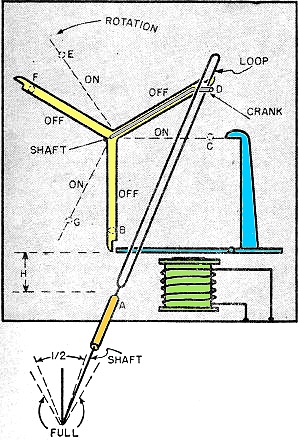 Fig. 1 - Three finger R/C escapement furnishing
three left positions, two right positions, and one neutral crank position.
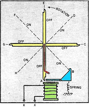
Fig. 2 - A four finger escapement with three left and three right positions, two
neutrals. This of course allows for more flexible control of a model airplane or
boat by radio control.
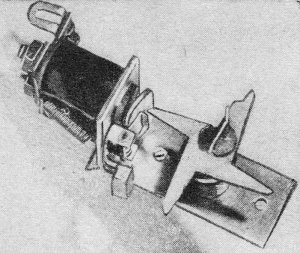
Fig. 3 - A four finger escapement. Fig. 2 shows its mode of operation giving three
left, three right. and two neutral positions.
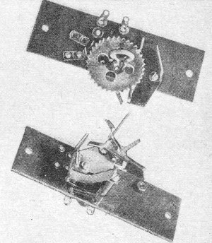
Fig. 4 - The Bonner compound escapement used for radio control. Notice the ratchet
wheel and rocker arm combination for smoothing out the rotation and the spring contacts
on the front view.
Why use this type of escapement? The reason is more control. If the distance
H is made equal to the distance from the shaft to the crank, the deflection of the
loop to the right and left will be equal in positions C and G. These are the first
and third "on" positions respectively, and represent the maximum deflection possible.
Now notice that the loop will be deflected in positions D and F, but not as much.
These are the first and second "off" positions. The B position is neutral; E is
so slightly left that it can be used as a neutral.
Thus, with this type of escapement, it is possible to have two positions to the
right and three to the left and also a single neutral. In steering applications
a rudder may be placed in the "half" positions and allowed to remain there as long
as desired without consuming power. One can also have full deflection in either
direction, but only while the push-button is depressed. This is desirable particularly
in planes where sharp turns do not want to be sustained.
4-Finger Escapement
A typical four-finger escapement is shown in Figs. 2 and 3. This type is popular
for boat steering. The catch points of this escapement move the arms in 45-degree
jumps instead of the 90 degrees of previous types. This type of escapement will
provide three positions left or right, as shown in Fig. 2.
To remember just how many times to push the button to get a particular deflection
will be a problem. It is possible, however, to design a ground control unit which
will send forth the correct sequence for the position desired merely by moving a
steering lever or wheel to the left or right.
Compound Escapement
To simplify the ground control unit and yet allow particular signals to be transmitted
for left and right (and one other function), the Bonner compound escapement was
developed. (See Fig. 4.)
The sequence of signals is simple and can be readily performed with a push-button.
Pushing the button once will give "left." Holding the button down will prolong this
position. To obtain "right," push the button down; release, and down again. Hold
it down as long as you desire "right." For the third function, the sequence is "on-off,"
"on-off," "on." If one sends two quick pulses for "right" and desires to repeat
"right," he just sends the same two pulses as before. The same applies to "left,"
or to the third function. This is possible because the escapement is designed with
only one neutral or starting position. It returns to this neutral automatically
whenever the signal remains off for any length of time. Other escapements can be
made to do this, but require that a "neutral" command be transmitted after the steering
command ends.
How does the Bonner compound work? Refer to Fig. 4. Notice that the fingers are
not symmetrically spaced. This is done to allow the crank to be positioned left
or right by the "on" catch point only. Notice also that the finger to which the
crank is attached is offset. The "off" armature catch point is also offset to intercept
it alone. Thus, in the signal "off" position, this finger is intercepted by the
armature catch point and this corresponds to the neutral steering position.
Assume that the escapement has a rubber-band attached and is ready to operate.
Refer to Fig. 5. If a signal is transmitted, armature Y pulls down releasing the
offset finger. At the same instant, the "on" catch point moves in and finger 3 is
intercepted and held. This is "right." If now, the signal is turned off, this catch
point moves back, releases finger 3, and the shaft rotates clear around until the
offset finger (1) again en-gages armature Y. The steering element has returned to
neutral.
Notice the front of the escapement with its ratchet wheel and rocker arm that
engages the teeth on the ratchet wheel (Fig. 4). This prevents the escapement shaft
from snapping from one position to another. It causes the fingers to move around
at a definite speed.
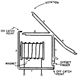
Fig. 5 - Diagram of the Bonner compound escapement in the
neutral position. For example, to obtain "left," a signal is sent causing armature Y to pull down.
Finger 3 is intercepted by the "on" catch point. Now, assume the signal is broken
for just an instant and transmitted again. The rocker prevents the shaft from snapping
around and so, the "on" catch point which moved back when the signal was broken,.
now moves forward again before finger 4 can get by. While the catch point holds
finger 4, the crank is "left." If the signal is turned off momentarily and on again,
the offset finger slips by, but finger 2 is caught and held. The crank is almost
at neutral and there is no steering, but another part of the escapement now enters
the picture to do another job.
Right behind the ratchet wheel is located a set of spring contacts which are
now closed by a tiny nub on the bottom of the wheel. This can close a circuit to
operate the extra function, which can take the form of a motor speed control, reversing
control, gas feed control, etc., depending on the type of model controlled.
END
Posted May 7, 2022
(updated from original post on 10/19/2011)
Vintage Popular Electronics Magazine
Articles-
Simple Dual Proportional R/C System - September 1956
-
An Experiment with Gravity, January 1970
- R/C Notes, January
1956
-
R/C
Triplex: Three Controls on One Channel, November 1956
- R/C Reliability,
March 1955 Popular Electronics
-
Robot Helicopter, November 1956
-
Model Boat for the 27 mc. Citizens Band , March 1953 Radio & Television
News
- Adjusting
the Power - R/C Plane, January 1955
- Rejuvenate
R/C Batteries, July 1955
- 3 and 4 Finger
R/C Escapements, January 1955
- Radio Control
of Models, October 1954
- The R/C Cloud,
February 1960
- Radio
Control Installations, February 1955
-
Compound
Escapements & Servos, February 1955
- Flying the R/C
Plane, December 1954
- The Lorenz
Transmitter, December 1954
|

