|
One thing you can be pretty sure of when looking at airplane model articles in 1954-vintage magazines
is that they are either free flight, static display, or control line. Radio control was still
very new at the time and it was largely the realm of experimenters and guys who were willing to
risk a lot of building time and effort on what would almost certainly eventually end in disaster.
So, when I saw this construction article for a nice 68" wingspan, 4-engine B-4 Liberator, I knew
it would be for control line. Although finding a copy of the original plans will be a challenge,
the version I scanned along with the construction article high enough resolution to scale up for
use. These plans are not guaranteed to be true to scale, but they do result in a really nice looking
B-24. Have fun. Part two, which includes instruction for adding scale detail, appeared in the
September 1954
edition.
Model This B-24 Liberator
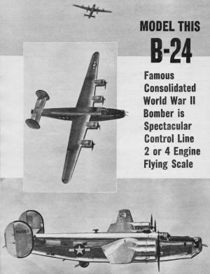
Famous Consolidated B-24 Liberator World War II Bomber is Spectacular Control Line 2- or 4-Engine
Flying Scale |
By Frank Lashek with S. Calhoun Smith
Part I presented here will deal with construction of the B-24 model. The forthcoming Part II
will explain scale details and markings.
World War II scale model fans will welcome this addition to the flight circle. The once mighty
Liberator really lived up to its name. Mainstay of the Air Forces in all the operational theaters,
the big bomber delivered countless tons of destruction to the enemy.
Like any of the World War II aircraft the B-24 underwent many modifications. The particular
version presented here is the B-24H-FO, built by Ford at Willow Run.
While not large by today's standards, the B-24 spanned 110 ft., and this version was 67' 2"
long. The power was four Pratt Whitney R-1830-65 engines, supercharged to 1200 hp. Armament consisted
of four power turrets with twin .50 cal. guns and single .50 cal. guns in waist positions. Bomb
load varied from four to five tons depending upon mission. Crew usually numbered 10 to 12 men.
Top speed was 270 mph, service ceiling 36,000 ft. and range with substantial bomb load, 2,600
miles.
This model is no beginner's project and because of its size construction will take some time.
It can't be built over a weekend. Scale is 5/8"= 1", giving model a span of 5 ft., 8 3/4 in. Length
is 42 in. The model has been flown with various power combinations, and because of nacelle size,
the builder has a wide choice of engines. Original power was four ignition Bantams. Performance
was good, but weight was quite high so that two or three engine flight wasn't too satisfactory.
Later, two glow K&B .19 engines were fitted in inboard nacelles only. By eliminating nearly
a pound of ignition system weight, the two glow plug 19's equaled four Bantams.
Weight of model is 4 1/2 lbs. without engines. This is pretty light for such a big job. If
the builder can come close to this weight, two .19 engines will be enough power. If the model
is heavier, larger engines will be needed such as two .23's or .29's. If four engines are desired,
four .19's will be adequate. All-up weight with four .19's should be close to six lbs. The nacelles
are large enough to accommodate any of these engines: K&B, Fox, O&R and Cameron. The limiting
factor is prop clearance, 9" dia. prop being the largest permitted by scale nacelle location.
Ground-prop clearance is only 7/8" with 9" props, so the builder might wish to lengthen landing
gear slightly, use larger diameter wheels or clip prop tips for more clearance above ground.
Flying on two engines the B-24 model looks exactly like the real bomber. |
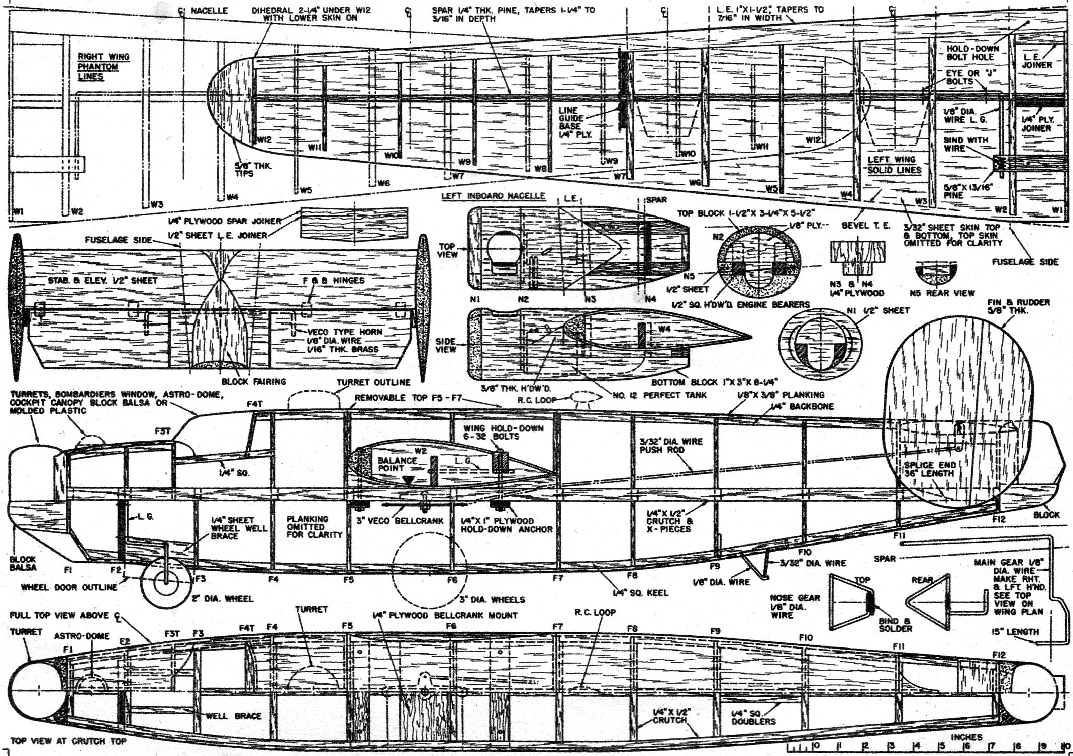
Construction follows standard practices. Fuselage is crutch and former with strip planking.
Wing has heavy leading edge and spar with sheet skin, tails are solid sheet. Wing has been made
removable from fuselage for ease of transportation. Unless you have a station wagon this feature
should be included.
One of the main difficulties with multi-engine models is vibration caused by engines running
slightly out of synchronization. Therefore the nacelle construction is quite rugged. Also the
nacelles must be joined firmly to the wing structure. You will note the liberal use of hardwood
in nacelles and wing.
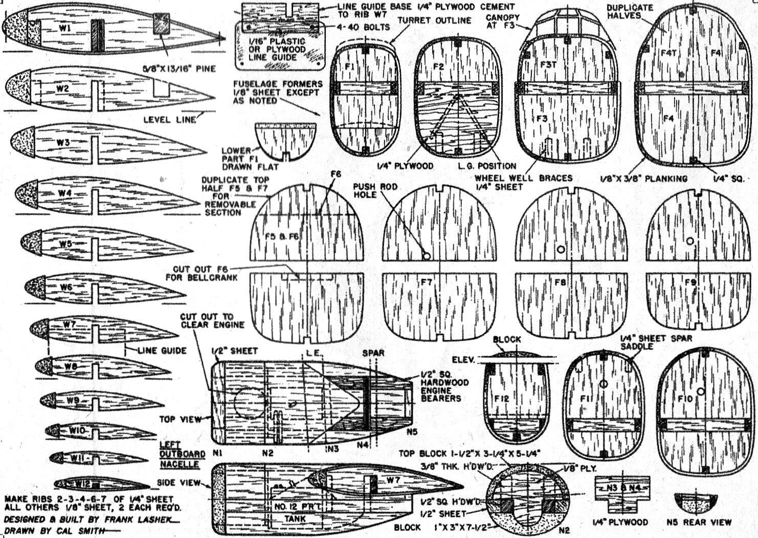
Building can be started with the fuselage. Cut out all formers; these consist of top and bottom
halves and where width is greater than 3" sheet, former can be divided at center line for ease
of duplication. Lay down crutch and cross-pieces over plan top view and add bottom halves of formers.
Nose gear, wing hold-down strips, bellcrank mount and tail skid should be put in place before
adding planking. Whole bottom can be planked before removing from work board. Top formers can
now be added to the top of crutch. Proceed with planking along sides to maintain rigidity. Leave
top open until pushrod is fitted.
Carve stabilizer and elevators to shape, fit horn to elevators and join elevators to stabilizer
with hinges. Fit stabilizer to fuselage top and pushrod. Tail can then be laid aside until fuselage
planking is completed. It can be joined permanently later. Removable section above wing can be
planked along with rest of fuselage. Place a layer of waxed paper between duplicate formers F5
and F7 so that section can be removed easily. Carve lower edge to fit wing curve later when wing
is completed. Add 3/8" sheet along crutch top to form wing saddle between formers F5 and F7. Carve
to fit wing later. Cement blocks in place below nose and tail turrets next. Carve to shape, blending
into fuselage lines. Entire fuselage can be sanded smooth now. Apply two coats of clear dope,
sand smooth, then cover fuselage with Silkspan. Fuselage final finishing will be done later.
Wing construction comes next. Cut out ribs first; note that some are of 1/4" thick stock, These
are at nacelle locations for added strength. The leading edge should be hard balsa; it tapers
in width from 1" to 7/16", and from 1 7/16" to 3/8" in depth. The taper can be shaped before adding
to structure or after it is cemented in place. Spar is pine or similar hardwood for strength at
gear and nacelle locations.
Drill spar for landing gear and eye or J bolt attachment, then lay spar down over wing plan
and put ribs in place. On rib plans you will notice a "level line" below rib ends. These indicate
workboard surface with spar resting thereon. Use lines as guide to blocking up leading edge and
trailing edge. Cement ribs in place to leading edge and spar. Plank top surface with structure
still down on workboard. Repeat procedure with other wing. When dry the two wing halves can be
joined with plywood and block joiners.

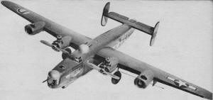
Designer and builder Frank Lashek with the first 4-engine version powered by ignition Bantams.
Model more recently has been operating on two glow plug motors. |
Now add pine strip for hold-down and rear landing gear attachment. Bend main gear to shape and
push into place along front face of spar. Attach with eye or J bolts. Pine strip at rear should
be notched 1/8" deep on bottom surface to receive rear end of landing gear wire. Carve pine flush
with top skin, drill vertically and bind with soft wire of about 1/32" dia. Cover binding and
also. the landing gear wire end with cement.
Lower surface of wing can now be covered with 3/32" sheet, beveling trailing edge of sheets
for smooth fit. Add tip blocks, then carve tips and leading edge to final shape. Sand entire wing
smooth; clear-dope and paper-cover. Carve center section leading and trailing edge square to fit
space between fuselage formers F5 and F7. Drill for hold-down bolts. Carve wing saddle in fuselage,
put wing in position and mark hold-down strips for bolts. Hold-down nuts soldered to strip of
tin are positioned under strips.
Next make nacelles. Space engine bearers according to engine used. Plans show spacing for K&B
.19 power.
Locate engine mounting holes in the bearers, make nut plates and put in place. Relieve bottom
block for nut plates and glue bearers to bottom block. Fill along sides of bearers with 1/2''
sheet. Rough-carve bottom shape, then hollow to accommodate fuel tank. No. 12 Perfect tanks are
used but tubing is repositioned so that tank is placed with narrow side down. To help join nacelle
to the wing, triangular pieces of 3/8" thick hardwood are positioned below leading edge, along
top of engine bearers. The underside of leading edge should be notched slightly to receive the
hardwood. Plywood bulkheads at rear of leading edge and spar help to strengthen nacelle wing joint.
Glue bulkheads to leading edge and spar, then fit nacelle to bottom. Where hardwoods join in
this assembly use hard glue such as Weldwood. Some cutting and fitting will be needed to match
up all the surfaces here. On outboard nacelles the top of engine bearers clears the bottom surface
of the wing and some packing will be required. The inboard nacelles are a bit different, the engine
bearers being above the bottom surface, so the engine bearers, the lower skin and spars will have
to be notched a bit. Note that nacelles are level with ground and therefore at an angle in relation
to wing dihedral. See nacelle section N2.
Top portion of nacelle is carved from block, carve inside to fit over firewall N2. Portion
behind N2 can be cemented permanently in place after tank and tubing is installed. Top portion
ahead of N2 can be made removable if desired for access to engine. Front face of nacelle is shaped
from 1/2'' sheet and cemented to front of engine bearers and bottom block.
Line guide base is piece of 1/4" plywood cemented against outside. face of rib W7; cut through
bottom skin to set in position. Line guide itself can be plastic or plywood. It is bolted to base
so that guide and leads can be taken off wing easily, when wing is removed from fuselage.
Only remaining woodwork is the rudders. These are carved from solid stock, and can be joined
to stabilizer now or after finishing. Cement stabilizer in place on fuselage rear and add fins
and rudders as desired. Mount rudders with about 1/2'' offset to right. Add block fuselage fairing
on top of stabilizer and turret fairing over center section of elevators.
Finishing and scale details will be taken care of in Part II.
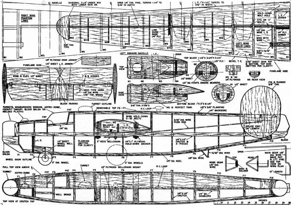
Consolidated B-24 Bomber Control Line Model Plans - Main
Frame
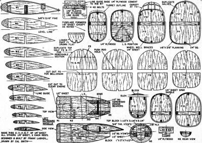
Consolidated B-24 Bomber Control Line Model Plans -
Ribs and Formers
Bill of Materials
40 - 1/8" x 3/8" x 36", fuselage planking 8 - 3/32" x 3" x 36", wing skins 5 - 1/8"
x 3"x 36", fuselage formers and wing ribs 1 - 1/4" x 3" x 36", wing ribs 3 -1/4" x 1/4"
x 36", fuselage keel and backbone 4 - 1/4" x 1/2" x 36", fuselage crutch 2 - 1" x 1 1/2"
x 36", wing leading edge 2 - 1/4" x 1" x 36" (pine), wing spar 1 - 5/8" x 3" x 36", fin
and rudders, wing tips 1 - 1/" x 3" x 36", stabilizer and elevators, nacelle fronts 1
- 1" x 3" x 36", nacelle bottoms 1 - 1 1/2" x 3" x 21", nacelle tops 1 - 1/2" x 1/2" x
36" (hardwood), engine bearers 1 - 5/8" x 13/16" x 6" (hardwood), rear landing gear mount
1 - 8" x 9" x 1/4" plywood wing joiner, line guide, landing gear former, nacelle former, bellcrank
mount, wing hold-down 1 - 6" x6" x 1/8" plywood, nacelle formers Scrap blocks for turrets,
canopy, fairings 2 - 36" length 1/8" dia. wire, landing gear, elevator horn, skid 1 -
36" length 3/32" dia. wire, pushrod, skid 2 - 36" length 3/64" dia. wire, line leads 3"
Veco Bellcrank, one 2" dia, wheel, pair 3" dia. wheels, 9 Eye or "J" bolts, four 6 - 32 x 3 1/2"
bolts, four F&B elevator hinges, two or four #12 Perfect tanks, cement, Weldwood, clear dope,
tissue, primer, olive drab, gray dope, decals as needed.
Full-size plans for the B-24 are a part of Group Plan #854 available from Hobby Helpers, 770
Hunts Point Avenue. New York 59, N.Y. (50c)
Posted March 29, 2014
|