Melanie modeling my version scratch-built from plans (not a kit).
My Lorraine grandmother (grandfather) clock built from plans and mechanics purchased
from Klockit is complete after nearly four years. For as long as I can remember,
I have wanted to build a floor model clock, and this one will fit well in our 1,500
sq.ft. split foyer house. The wood chosen is hickory both because it has beautiful
grain and color variation, and because then I can say that I have built a "Hickory
Dickory Clock!"
The hickory was bought from Summit Hardwoods,
just a few miles south of Erie, PA. Thus far I have cut out most of the rectangular
blanks. Finally, the process of squaring everything and exacting the dimensions,
then the detailed shaping, drilling, routing, sanding, etc., has paid off in the
form of a beautiful, classic grandmother clock.
Although I enjoy the building and finishing process, I can't wait to hear the
tick-tock of the weight-driven clockworks, and the hourly chimes. My obsession with
the passage of time is pacified for the time being with a refinished antique wall
regulator, but this is my piece pièce de résistance.
The instructions and drawings provided on the plans are excellent, but as the
old adage goes, a picture is worth a thousand words (not sure how many drawings
a picture is worth, though). There have been a couple instances so far where the
order of operations would be better with a couple steps changed. One example is
where milling the 1/4" cove in the Hood's arched piece (H-8) over the door is necessary
prior to hinging the door because otherwise the door cannot swing shut. Another
is that I decided to glue the crown pieces directly to the hood rather than build
the crown assembly separately and then screw it to the hood. There is also the case
in Step 28 where the wrong edge of Hood bottom is indicated on the plans.
Latest update August 10, 2013
The Lorraine Grandmother Clock project is officially complete! All four 1/8"
thick glass panels were cut by Schaal Glass Company here in Erie, PA. They did a
great job with the arched piece that goes in the door for the dial. If I had though
it out before-hand, I would have modified the plans to use just a simple arch to
make glass cutting simpler (and less expensive). There would still be a shoulder
region per plans when viewed from the front, but the inset for the glass in the
back of the door would have just an arch from one side to the other. A complete
set of photos of the finished clock will be posted soon. Here is a short video tour
of the completed Lorraine Grandmother
Clock!
July 27, 2013 Update
The Lorraine Grandmother Clock is complete and has been fully operational of
of July 27, 2013! The only thing left to do is install the glass panels, but I'm
waiting to have them cut. Doing a complete mock-up of the mounting and fitting prior
to finishing made for very quick work installing all the clockworks components and
panels. A very slight adjustment of the chime hammers was needed, but that's it.
I pulled the pendulum to the side and let go, and it's been ticking away ever since.
Thus far it appears to be keeping perfect time. The moon dial has been set for today's
moon phase, so it will be interesting to watch it progress over the next month.
planning for the clock began in November of 2009 when I purchased the plans from
Klockit - about 3 years and 9 months.
Melanie did a great job filming a short video on me explaining my method for
applying polyurethane without suffering the heartbreak of runs, sags, and air bubble
in the finish. That is a hot topic in online forums and as you might expect, there
are many opinions, often contradictory, on the best way to do it. My way has been
honed over many decades and works well for me, but it might not be the best way
for everyone. Melanie made a video of me talking through my process of
applying the polyurethane
in a manner that eliminates bubbles, sags, and runs.
Installing finial mounting
stud. Put nut on finial end and use a socket to screw into wood, then screw finial
onto stud. Doing so prevents potential stripping of finial threads. Use way on wood
thread end to ease installation.
Using a dab of wax on
screws during installation makes them much easier to install, especially in hardwood,
and minimizes the potential of wringing the head off. I pre-drilled and pre-threaded
every screw hole prior to finishing, but still used wax for final assembly.
Using a square screwdriver
bit to adjust the friction-fit center hub of the minute hand simplifies the job
Base with polyurethane
applied. A full four coats were applied to inside surfaces as well as to outside
surfaces.
Chime Block mounted on
Hood. Hood rear cover.
Lorraine Grandmother Clock
built from Klockit plans. Finish applied and ready for clockworks (rear view).
Hermle Grandmother Clock
Movement Model #451-050 (left side)
Hermle Grandmother Clock
Movement Model #451-050 (right side)
Hermle Grandmother Clock
Movement Model #451-050 (back)
Hermle Grandmother Clock
Movement Model #451-050 (front)
Hermle Grandmother Clock
Movement Model #451-050 (top)
Hermle Grandmother Clock
Movement Model #451-050 (bottom)
Hood and crown after
finishing (top view)
Clockworks and supporting
frame, and side panel fabric frames
Even the bottom received
stain and polyurethane
Hood and Crown with stain
and four coats of polyurethane (front view)
Hood and Crown with stain
and four coats of polyurethane (rear view)
Inside of base
Minwax Early American
#230 stain applied (front & rear views)
Minwax Early American
stain applied (hood rear)
Minwax Early American
stain applied(base rear)
Gluing/clamping crown
molding
on Waist Top Cap
Gluing/clamping crown
molding on Base
Base rear plywood cover
screw countersinking
Dial mounting - front
Dial mounting - rear
Dial and chime block
mounting
Clamping Base side panels
Base assembly plywood
Waist assembly clamping & gluing
Waist and Base side components with rabbets and dados cut.
Base bottom assembly - top view.
Base Steps 12 - 15: Base bottom with corner and triangle gussets
installed.
Waist Steps 1m & 1n: Cutting the cove molding on the table
saw.
Waist Steps 31 - 34: Top waist cap being glued.
Base Step 2 & Waist Step 5: Cutting dado slots in side members.
Waist Step 1j: Ripping jig for cutting cove molding triangles
from square blank.
Waist Step 1k: Cove molding shaped and ready for cutting interior
curve.
Push tool made for cutting concave in cove molding. Notch engages
corner.
Crown Step 50: Crown trim glued to front.
Gluing Crown components to Hood. The plans say to build the Crown
separately and then screw it to the Hood, but I decided to glue everything as I
went along in order to make it easier to fit pieces together properly.
Hood Step 60: Crown molding parts C4 & C5 mitered.
Hood Step 33: Hood corner columns.
Crown Step 49: Scrap wood attached to Crown part C4 while routing.
Fitting Crown molding parts C1 & C4.
Hood Step 32: Cutting arch in Hood side piece H-2L. I performed
this operation right after Step 4.
Hood side and door pieces.
Hood Steps 34-36: Hood grill cloth frame and door glass retainer.
Using drum sander to smooth Hood side piece arch.
Hood Step 25: Close-up of Hood left side with door hinge.
Hood door arch sanding template.
1/4" round edge milled in Hood door arch.
Hinge slots for Hood door.
Hood Step 31: Rabbet for Hood door glass milled on back side
of door.
Milling rabbet in Hood piece H-10.
Major Hood components screwed together for test fitting.
Hood Step 26: Milling hinge slot in piece H-1R for Hood door.
Hood frame components clamped for screwing. Note 2" square grid
etched into workbench surface to help make alignments easier.
Scrap wood extensions butted against Hood arch piece H-8 so that
router bit does not walk around corner at bottom of arch.
Plywood pieces H-14 and H-17 screwed onto Hood frame. Hole for
clock movement has not been cut out of H-14 yet.
Hood Step 32: 5/32" Roman ogee milled into Hood side openings.
Close-up of 5/32" Roman
ogee.
Video Tour of My Lorraine Grandmother
Clock
Applying Polyurethane Finish to the Lorraine Grandmother Clock
(video)
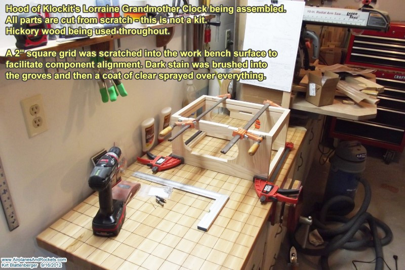
Update September 16, 2012
At long last, most of the major house projects are done so I'm finally able to
get back to work on the clock! Oh, part of the delay has been due to moving to a
new house in December 2010. The workshop is set up in the garage of the new house
rather than in the basement as the previous one was. It's nice having an 8-foot
high ceiling again. Before beginning assembly of the clock's hood (top enclosure
for the works and dial), I took the time to scratch a 2" square grid pattern on
the workbench surface. Dark stain was brushed into the grooves and then a couple
coats of clear were sprayed over everything. This will make getting all of the clock
components straight and square much easier. The clock's hood assembly is being clamped
and screwed at this point. The plans don't call for glue on any of the frame joints,
but I will put some on prior to final assembly of each section. Trim pieces in future
steps will hide all of the screws in the frame so it will not be necessary to plug
the screw heads. It has been a long time since I undertook a project like this where
precision cutting and sanding is required for everything to fit properly. Buying
a much better belt/disc sander has made keeping edges square and straight much easier
(the old 3" model was a real piece of junk that would stall if I pushed down on
the wood with too much force).
Update November 12, 2010
Well, I thought all the blanks had been cut, but after reading through all the
plans pages, I found about 20 more pieces that were not shown on the main cut-out
drawings. Most were pieces that had at least one dimension less than the stock 3/4",
so it required running the wood across the jointer to trim it down to 1/2" or 1/4"
as specified. I just bought a Craftsman 4-1/4" jointer, and man do I ever appreciate
that machine! The last time I used one was in high school woodshop back in the mid
1970s.
Now that all the blank slabs have been cut and sanded to precise size, the next
step is to begin doing all the mitering, jointing, routing, and assembling. I also
bought a Craftsman router and router table to make the job easier. The table saw
or radial arm saw could be used, but the router table setup will be much more precise
when handling the relatively small pieces in the clock. Building a cabinet or bed
frame would be a more appropriate size for using the saws.
Well, Melanie and I just signed a contract on a different house here in Erie,
and we're due to close on it at the end of November, so unfortunately that means
packing up everything and moving before getting back underway.
The house has 1,500 sq.ft. as opposed to our current 910 finished sq.ft. (plus
full unfinished basement - see photos
here). The new house is a split foyer type, so the workshop will be downstairs
on the garage level It is about 25 years old, but in very good condition. One of
the best features is that it is one of the very few panoramic views of Lake Erie,
from a vantage point high on a ridge line. The only thing better would be to live
right on the shore, which, of course, I cannot afford. I will post pictures later.
Whereas the workshop here is just kind of thrown together, in the new place I
will build wooden work benches and tool stands permanently into the lower level,
and there will be ample overhead lighting along with a distributed dust collection
system - nothing too elaborate; just enough to keep from having to move the shop
vac around all the time.
So please check back around the end of December 2010 for an update. Have a
HappyThanksgiving and a
Merry Christmas!
Even during the busiest times of my life I have endeavored to maintain some form
of model building activity. This website has been created to help me chronicle my journey
through a lifelong involvement in model aviation, which
all began in Mayo,
Maryland...
Copyright 1996 - 2026
All trademarks, copyrights,
patents, and other rights of ownership to images and text used on the Airplanes
and Rockets website are hereby acknowledged.