As
with most other aspects of aeromodeling, ducted fan propulsion systems
have come a long way since the time you had to build the entire
unit yourself. Modern prefabricated ducted fans are molded glass-filled
nylon or carbon fiber that has been engineered, manufactured, and
optimized in every aspect of strength-to-weight, thrust, and dimension
for the intended application and powerplant. It is like the difference
between early radio controlled
 helicopters
that were built on hand-drawn plans and built on a lathe and end
mill, and the models you can buy now that practically fly themselves
right out of the box. If you do, however, relish the thought of
designing and building your own ducted fan or if you just like learning
about how the pioneers developed the science into what it is today,
then this article is for you. helicopters
that were built on hand-drawn plans and built on a lathe and end
mill, and the models you can buy now that practically fly themselves
right out of the box. If you do, however, relish the thought of
designing and building your own ducted fan or if you just like learning
about how the pioneers developed the science into what it is today,
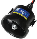
then this article is for you. The ducted fan unit to the
right is E-flite's
EFLDF15 electric motor powered unit. It costs a mere $30 from
Horizon Hobby. Using the purpose-built
BL15 brushless motor ($65) on a 3-cell LiPo, you can expect
1.7 pounds of static thrust at 31,000 rpm. Add another cell
in series and increase the thrust to a whopping 2.8 pounds at 40,000 rpm.
Ducted Fans - Scale-like R/C Planes
By P.E. Norman
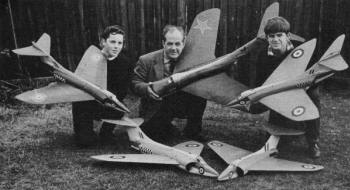
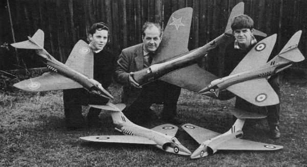
Author-experimenter P. E. Norman, son Marcus, friend, 5
R/C ducted fan models. |
Having been an ardent flying scale fan since I built my first model
plane back in 1925, it was with mixed emotions that I watched the
rapid progress in jet-plane development after World War 2, spelling
as it did the beginning of the end of the military prop-plane era.
No longer would there be such a wide choice of interesting new prop-driven
aircraft from which to choose new subjects for my scale activities.
But as the years went by and the post-war skies of Britain
became more and more the domain of jet-planes, these beautiful winged
projectiles soon cast their spell. I determined to build flying
replicas and join the Jet Age myself! This was in the early "Fifties"
when very little work had been carried out with model jets. As far
as I could ascertain, the ducted-fan appeared to offer the most
practical source of power ... especially for my own particular style
of model built very rugged to withstand plenty of wear and tear
as well as frequent contact with trees, buildings and Mother Earth!
Intake and efflux (outlet) sizes were an unknown factor,
but extensive bench tests with tubes and cones of various diameters
and tapers, showed that they would have to be of generous proportions.
Restricting the opening at either end caused a substantial drop
in engine rpm and "blow" from the rear end. So from the start all
of my D/F models featured monocoque fuselage construction to permit
the largest possible size fans to be fitted. Observation of other
D/F craft have confirmed that those equipped with small fans (in
relation to maximum fuselage cross section) usually have marginal
performance. Most seem incapable of ROG fights or of gaining much
height after being launched from shoulder level.
Boulton Paul 121. |
With all my models I have always tried to approach something like
scale speed, so they usually fly fairly fast and are heavier than
the average F/F scale type. To continue the same kind of operation
with D/F models, I would have to squeeze every possible ounce of
thrust from the powerplants. Which led me to the next unknown factor
- the actual fan. My first fan of bent aluminum was discarded at
an early stage of testing when a blade flew off at peak rpm and
just missed my foot. Fan Design ... Among
the materials I tried for fan blades were 1/16" plywood (quite good),
tufnal, cut-up, plastic bottles (too flexible) and finally fiber.
Fiber turned out to be ideal, so I have used it exclusively with
blade thicknesses varying from 1/32" to 3/32". Fan blades should
be cut slightly oversize and secured in the hub slots with resin
glue and small brads through the hub face. When dry, a disc is bolted
to the front of the fan so surplus portions of the blade tips can
be trimmed off. Blades should be bent gently into a slight camber
and then given several coats of fuel proof dope for protection against
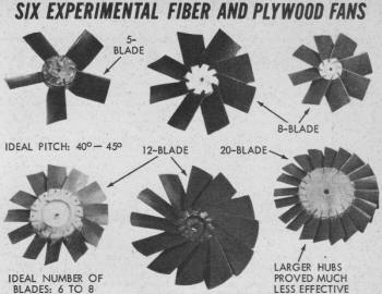
warps and oil soakage. I have tried dozens of different
fan designs, with 3 to 24 blades of various width and pitch setting,
in combination with different hub diameters. Best results have been
with 6 and 8·bladed fans (1" to 1 1/8" width). set at 40· to 45°
pitch in reasonably small hubs. Fan hubs are cut from 3/8" thick
plywood and accurate blade installation obtained by using a simple
jig for aligning hub-slot locations correctly. I make such a jig
from a 1" wide strip of 1/16" aluminum. A hole of the same diameter
as the engine crankshaft is drilled close to one end of the strip,
which is bolted firmly to the plywood hub (already marked with the
blade positions on one face). The strip is bent over at right angles
(so that it rests flat against the circular edge of the hub) and
cut off about 1/2" beyond hub's rear face. A 40° or 45° slot is
cut in the bent-over portion of the strip with a hacksaw and the
hub rotated until the first penciled-in blade location is lined
up with the strip-slot. Then the assembly is secured in a vise and
each hub-slot cut to the desired depth.
 A
carefully assembled fan is important, since perfect balance is essential
for maximum fan efficiency. Originally I used "diesel" (compression
ignition) powerplants, but changed to glo-engines when I found the
latter gave much more thrust due to high operating rpm. A large
Volume of air moving through the duct at great speed is desirable
- with as little restriction as possible in the area behind the
fan and at the efflux (rather than a large Volume of air being drawn
into the fan and then being compressed and exhausted through a restricted
efflux). A
carefully assembled fan is important, since perfect balance is essential
for maximum fan efficiency. Originally I used "diesel" (compression
ignition) powerplants, but changed to glo-engines when I found the
latter gave much more thrust due to high operating rpm. A large
Volume of air moving through the duct at great speed is desirable
- with as little restriction as possible in the area behind the
fan and at the efflux (rather than a large Volume of air being drawn
into the fan and then being compressed and exhausted through a restricted
efflux). Fuselage Design ... My first ducted-fuselages,
built almost exclusively of balsa, consisted of 1/8" x 1/4" planking
over 1/8" sheet assembly formers (later removed). Upper and lower
halves were each made in this way then cemented together and covered
with light silk doped in place (after first covering the interior
with similar material). However. this method was prone to soak up
fuel with a consequent reduction in strength and a marked increase
in weight after a few flying sessions. Obviously this wasn't
the solution, so next I tried papier-maché (paper-pulp mixed
with glue) fuselages, but this also suffered from similar defects.
Fiberglass molded bodies proved fairly satisfactory, although they
tended to come out on the heavy side and were likely to fracture
upon a sudden heavy impact. Eventually I turned to 1/32"
plywood, soaked in water to make it flexible (again using 1/8" sheet
assembly formers). Although this is more difficult to form (except
in very simple curves), it proved the best all-round construction
method since it is fairly light and highly resistant to oil soakage.
So all my subsequent D/F models have had bodies of this type. The
fuselage forward of the wing position should always be the strongest
part of a D/F model - and you can afford the extra weight since
nose ballast is usually required anyway. Resin glues (liquid or
powdered) are used, extra strength is obtained in larger models
by using two or three laminations of 1/32" plywood, reinforced by
light nylon or nylon-chiffon attached with the same adhesive. All
hinges, for powerplant, R/C equipment or other items, can be made
from nylon ribbon.
Flying
Surface Design ... Conventional building methods proved
satisfactory for wing panels, stabilizers and fins, although I install
3/16" diameter reed along the wing leading edges and around the
tips as with all my scale models. Full depth mainspars of hard 1/8"
balsa, strengthened by gluing 1/32" plywood on one face, provide
a very tough wing structure. Thin, flat-bottomed sections
should be used for the wings, installed at 1.5° to 3° to the thrust-line.
High set stabs usually require a similar amount of negative incidence.
Wing boxes are best made from 1/16" or 3/32" plywood, with hard
1/4" wide balsa spacers at the edges and the complete boxes securely
bound and glued with nylon thread. Knock-off wing panels
and stabilizer are best, wings being retained by built-in spring
clips, the stabilizer by rubber bands stretched over the top from
hooks set in fin leading and trailing edges. The latter is for high-mounted
stabs. When the stab is lower or on top of the fuselage, separate
knock-off stab panels can be mounted in a similar way to the wing
panels. It's usually best to mount the fin integral with fuselage.
light silk covering, or preferably nylon-chiffon, is ideal.
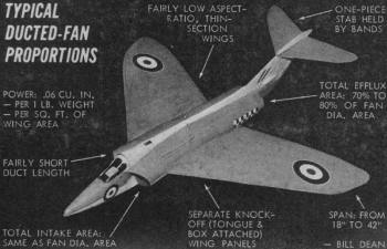
 Powerplant
Considerations ... A good guide to the amount of power
required is to aim for .060 cu. in., per 1-lb weight, per sq. ft.
of wing area. This is assuming a well-streamlined clean design with
a fairly low aspect-ratio wing. Keep in mind that long fuselage
ducts have the disadvantages of increased air-friction and weight,
so keep ducts as short as possible. Although air-flow straightener
vanes (mounted at an angle of 30° close behind engine on a streamline
balsa cone) do increase thrust slightly, they also make duct cleaning
difficult. Down-thrust-vanes of 1/32" plywood should be installed
in the extreme end of the duct efflux to permit power flight trimming. Powerplant
Considerations ... A good guide to the amount of power
required is to aim for .060 cu. in., per 1-lb weight, per sq. ft.
of wing area. This is assuming a well-streamlined clean design with
a fairly low aspect-ratio wing. Keep in mind that long fuselage
ducts have the disadvantages of increased air-friction and weight,
so keep ducts as short as possible. Although air-flow straightener
vanes (mounted at an angle of 30° close behind engine on a streamline
balsa cone) do increase thrust slightly, they also make duct cleaning
difficult. Down-thrust-vanes of 1/32" plywood should be installed
in the extreme end of the duct efflux to permit power flight trimming.
Getting down to cases for typical model! powerplant combinations:
18" to 24" wing span suits .049 engines; 24" to 30" span for .09's;
30" to 36" span for .15's and 36" to 42H spans for .19''s. Most
of my D/F flying with American powerplants has been carried out
with Cox and Fox products. Typical fan-diameter/powerplant
combinations are 3" for .049's; 3 3/4" for .09's; 4" to 4 3/8" for
.15's; 4 1/2" to 4 5/8" for .19's. For 3" dia. fans, 6 blades should
be used - 8 blades on anything larger. Both 3" and 3 3/4" fans (1/32"
thick blades) need 40° pitch - while the larger sizes (1/16" thick
blades) can take from 40° to 45° pitch. It's worth while
making up several fans of varying pitch and picking out that best
suited to a particular model, after flying tests. Although there
is quite a bit of work involved in these fans, remember that the
chance of breaking one in a crash (except in a complete write-off)
is very slim. A range of commercial fans of this type are made in
Britain by Veron - some U.S. mail order dealers carry them.
Intake area should be as close to fan-diameter as possible;
efflux area should be from 70% to 80% of the fan-diameter area.
Direct nose intakes or "elephant-ear" intakes (forward of wing)
are far more satisfactory than wing-root intakes. The circular intake
and efflux areas may be changed into elliptical shapes by cutting
1/2" wide strips of thin card and overlapping the ends to form circular
rings, then squashed slightly to provide the desired section patterns.
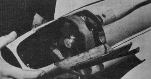
 Combined
plywood engine/wing-tongue/fuel-tank mounting-plates must be absolutely
rigid and well braced to the lower fuselage half to avoid any vibration.
For .049 to .09 engines use 1/8" plywood; for larger motors, 3/16"
plywood. Fan rings of 1/32" plywood (1" wide) should be glued to
inside of duct, with a minimum of fan clearance, to avoid blade
tip losses. Engine, fan and tank must be easily accessible for cleaning
and inspection, since the oily duct interior retains an amazing
amount of dirt and grass picked up during landings. Combined
plywood engine/wing-tongue/fuel-tank mounting-plates must be absolutely
rigid and well braced to the lower fuselage half to avoid any vibration.
For .049 to .09 engines use 1/8" plywood; for larger motors, 3/16"
plywood. Fan rings of 1/32" plywood (1" wide) should be glued to
inside of duct, with a minimum of fan clearance, to avoid blade
tip losses. Engine, fan and tank must be easily accessible for cleaning
and inspection, since the oily duct interior retains an amazing
amount of dirt and grass picked up during landings. It's
a good idea to fit engine exhaust stacks with very light aluminum
shrouds, to prevent dirt from entering the cylinder head. Engine
holding bolts should be locked to guard against vibration. All access
hatches must close flush and hold securely, since a hatch opening
in flight will most certainly result in a spin or dive-in.
Flying Ducted Fans ... Correct balance should
be obtained by adding weight (I use empty cement tubes) to the nose.
Before leaving the workshop, become well acquainted with starting
your engine by means of a cord starter, find the best needle setting
for maximum rpm and check the duration of the fuel tank. A D/F model
without landing gear should push itself slowly across the floor
under full power. In addition, to your usual tool kit, starter
battery, you should take along a spare starter-cord, glo-plugs and
fan. Before starting engine, remove from intake front anything which
might get sucked in and damage the fan or engine. If possible,
fly over reasonably long grass. Try to choose a time when a slight
breeze is blowing as these models tend to have a fast gliding speed.
Aim for a dead-straight glide, without any suggestion of a stall
- correcting any turning tendency by small celluloid or plastic
trim tabs attached to the rudder and one wing tip. Avoid maximum
power for the first few flights, as slight adjustments may be needed
on the downthrust-vanes (to prevent stalling) or to the trim tabs
(to correct too sharp a turning tendency). Types
Built ... Since turning to D/F models, I've built and flown
11 scale and 13 scale-like F/F types - followed by 7 near-scale
R/C types. These divide into four flying-surface configurations,
as follows: #1) Swept-wing; #2) Delta wing; #3) Swept-wing with
swept-stab; and #4) Deltawing with delta-stab. Of these, type #3
models have proved the fastest and most stable, with type #4 following
close behind - they need no dihedral, provided the stabs are set
high. All types have performed well and most models built are still
in good flying shape. Apart from the four general categories
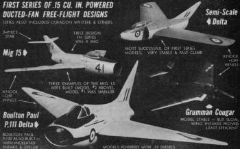
detailed, my D/F experiments have been concerned with three different
series of models. The first set included models from 30'" to 36"
span, usually powered with a .15 engine. My second series consisted
of smaller models of from 23" to 28" span each with an .09 or similar
powerplant. The third series covers most of my present D/F activities
- R/C designs from 32" to 44" span, powered with an engine from
.09 to .35 size.
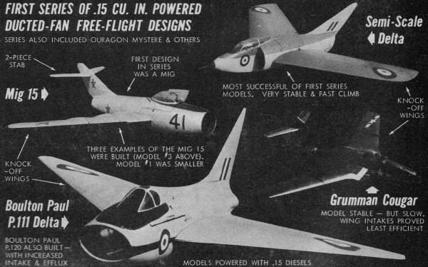
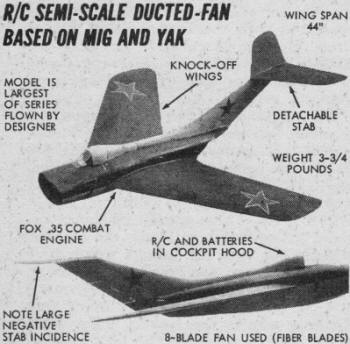
 Scale
Ducted-Fans ... the first F/F scale D/F model I tackled
was the MiG 15 powered by a .11 diesel (driving a 6-blade fan),
It had a span of 36", weighed 27 ounces and was very stable, with
a moderate rate of climb. This was followed by two more MiG 15's,
of slightly smaller size (32" span), but with more powerful .15
diesels. One used conventional balsa construction (like the first
MiG) and weighed 26 ounces; the other had a fiberglass fuselage
and weighed 29 ounces. Both differed from the original MiG in that
they featured integral fins and separate knock-off stab panels,
instead of a single knock-off fin/stab assembly. Scale
Ducted-Fans ... the first F/F scale D/F model I tackled
was the MiG 15 powered by a .11 diesel (driving a 6-blade fan),
It had a span of 36", weighed 27 ounces and was very stable, with
a moderate rate of climb. This was followed by two more MiG 15's,
of slightly smaller size (32" span), but with more powerful .15
diesels. One used conventional balsa construction (like the first
MiG) and weighed 26 ounces; the other had a fiberglass fuselage
and weighed 29 ounces. Both differed from the original MiG in that
they featured integral fins and separate knock-off stab panels,
instead of a single knock-off fin/stab assembly. These two
new models had greatly increased thrust output and really got up
there in a hurry. They were soon followed by a string of similar
proportion .15 diesel powered scale types - including the Boulton
Paul P.111 and P.120 deltas. Ouragon Mystere and the Grumman Cougar.
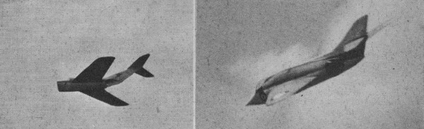
R/C Ducted Fans ... Some of the most exciting
flying I've ever experienced has been with R/C ducted-fans. They
are beautifully smooth in flight and respond to control immediately.
To date, I have only used rudder, but intend to try multi on future
projects. The present models are fast (about 50 mph). Since they
have little torque or gyroscopic effects they are quite easy to
fly. They climb well and settle easily into a fast, flat glide,
followed by smooth belly landings. Low passes downwind at a height
of 2 to 3 feet with a 50-60 mph groundspeed stir anyone who ever
nibbled cement off his fingertipsl My first D/F type fitted
with R/C was a .09 diesel powered delta-wing/delta-stab aircraft
of 32" span and allup weight of 28 ounces. A 4.5 volt transistorized
receiver was carried in the nose, pencells in the fuselage "spine"
and a very small home-built escapement housed in a fin-blister.
Initially flown in '59, this one took first place in an R/C spot-landing
contest and also made un-assisted ROG fights, using a take-off dolly.
A larger 36" span version of 350 sq. in. wing area was next powered
by a Cox .15 Olympic; she weighed all-up 40-0z. Subsequent
R/C designs have all been swept-wing/swept-stab using a Max .15
then a Fox .15 (34" span, 36 ozs.), Fox .19 (39" span) and Fox .35
Combat (44" span, 3.75 lb) powerplants. The .19 and .35 models develop
enough thrust for easy loops and wing-overs.
 Scale-Like
Ducted Fans ... Most of my F/F semi-scales have been based
on well known British, American and Russian jet-fighters. Sometimes
I borrowed features from different types to obtain characteristics
that fitted in with the type of model size/powerplant/fan combinations
I wanted. Scale-Like
Ducted Fans ... Most of my F/F semi-scales have been based
on well known British, American and Russian jet-fighters. Sometimes
I borrowed features from different types to obtain characteristics
that fitted in with the type of model size/powerplant/fan combinations
I wanted. Included among the more interesting semi-scale
D/F types I've turned out is a .15 powered Douglas Skyray delta
of 31" span and 30 ounces weight - built to obtain very large intakes
and efflux openings - with a thinner-than-scale fuselage nose, which
tapers sharply at the point it merges with the large intakes. It
flies at very high speed with a rapid rate of climb, has remarkable
stall recovery-the latter is an outstanding and rewarding feature
of all delta and tailless types. After many .15 powered
models, I decided to tackle a series of smaller designs, with a
view to closer scale speed performance. Although the larger ships
were quite fast, they did not reach 60 mph - which would be the
scale speed of a 36" span model when compared with a 36 ft. span,
700 mph-plus fighter. Since a 24" span model of the same type would
have to obtain only 40 mph for scale speed, I decided to "think
smaller" and this resulted in a delightful delta-wing/delta-stab
D/F of 27.5" span and 21 ounces weight. This model, dubbed
"Javahawk," was a blend of the British Javelin and the American
Skyhawk fighters. Fuselage and duct side profile consisted of a
straight underside and gently curved top to give built-in down-thrust
effect under power. It once turned in 7 minutes on the glide alone!
A lighter version can be trimmed to perform consecutive loops until
the fuel runs out. Both models definitely fly at scale speed!
Then there is a swept-wing/swept-stab job based on the Supermarine
Scimitar. Powered with a .09 diesel, spanning only 27" and weighing
20 ounces, this one has ultra-thin 5% wing panels and is very, very
fast. It belongs to the same "family" which culminated in the 34"
span, .15 powered "Rapier" F/F (or R/C) design - plans of which
are due to appear in a forthcoming American Modeler. In
a report of this type, I've naturally had to gloss over many points
of design and construction. Should you want to get the old drawing
board and start off with a D/F dream-ship of your own the "Rapier"
plans will fill in most of the gaps. But you'd be wiser to build
the "Rapier" first, as it incorporates the experience gained through
thousands of flights logged with more than thirty D/F models during
the past ten years.
Articles About Engines and Motors for Model Airplanes, Boats, and Cars:
Posted September 28, 2013
|