|
This treatise on engine idling techniques
is yet another example of how extensive and detailed model aircraft magazine articles
used to be. Maybe refinement in design and production has, over time, yielded engines
that are easier to start and and adjust, and are more reliable in general, but there
are plenty of older engines still in operation, whose owners could benefit handsomely
from the advice offered in this column. It has been my experience that even the newer
engines - particularly those typically purchased by those of us on a limited modeling
budget - still exhibit strange operation at times, so unless you always buy the best
engines on the market, read on... you'll be glad you did. Here is
Part 2.
Although aimed at radio control flyers this valuable data can be of help to
all modelers who own a glow plug powerplant...
Engine Idling Secrets
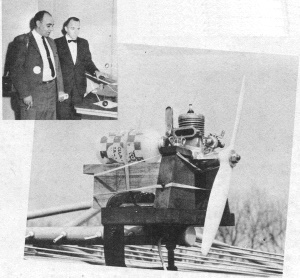 Researcher Thomasian (far lt.) with Dr. W.A.
Good. First clothes-reel test rig (bwloe); final rig considerably more sophisticated.
Part 1
By Harvey Thomasian
The appearance of glow plugs in engines did much to popularize the model airplane
hobby by eliminating almost all the evils of an ignition system. However, the glow plug
rates low for one condition that the ignition system did well: idle - glow plug engines
do not run happily at low R.P.M.
Hardly any information has been written on idling glow engines because theoretical
knowledge on the subject is limited. Many modelers know how to idle such an engine properly,
but not why.
In this report, we shall try to provide some insight as to the whys and wherefores
and present some information to enable modelers to adjust their engines for an acceptable
idle. We thought achieving an idle would be an easy task, but in studying the subject
seriously, we became convinced that any success was due more to good luck than skill.
This is not a complete how-to-do-it article. Our intent is to explain why and how
different factors affect idle, and we shall endeavor to explain how to best adjust your
engine to make it tick over slowly.
Although engine manufacturers have done much good work to achieve optimum low speed
operation, many factors outside their control make an occasional engine difficult to
idle. Also, engine design and materials have a marked effect. Some of these factors,
or variables, are compression ratio, base compression, glow plug design and material,
engine port timing, cylinder head design, heat balance, fuels, exhaust dampers, intake
throttles, temperature, humidity, altitude.
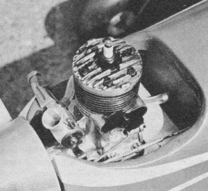
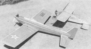
Nose of Thomasian low-winger shows aluminum mounting plate which permitted
different engines to be installed for flight testing.
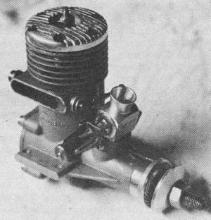
Super Tigre 51 has K&B intake throttle and rotary exhaust damper.
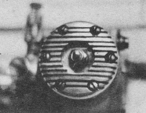
An S. T. 51 with fins cut into cylinder head.
Since these are just some of the factors, you can see it is extremely difficult to
make specific recommendations for all types of engines running on all the glow plugs
and fuels available, for all the different areas in this country with their peculiar
weather conditions. And quite honestly, the biggest variable is the modeler himself.
That's right ... you!
What we wish to emphasize here is that there exists no specific set of recommendations
which can be followed to achieve the desired slow speed. Also, any information provided
shies away from making major changes on engines since the manufacturers have done much
work to give their products a good balance between idle and maximum power.
Tests have been run on 31 multi-speed engines of 9 manufacturers. These tests were
conducted in the air with many models, as well as on the ground.
At the beginning of our tests, we had to decide on a target R.P.M. This was selected
as 2500 RP.M. which roughly gives zero prop drag at 14 m.p.h. with a 6" pitch prop and
around 10 m.p.h, with a 4" pitch.
Our ground testing was done by fixing an E-Z Just engine mount to the clothes line.
(This type of clothesline is mounted on a central pole and goes around and around). The
engine angle was adjustable about all three axes, could be mounted anywhere from the
center of the pole out to the end of one of the arms. This contraption was set up to
test the effects of centrifugal force, different engine and tank angles, at various radii,
and at all R.P.M.s, from idle to wide open. Although this rig did not completely duplicate
all flight conditions, actual flight tests showed that results from this whirlygig proved
out. It was especially helpful in determining if the engine would remain idling in a
spin and especially taught us a few things about fuel tanks.
The target R.P.M. figure is one where the engine will run the whole tank at idle:
2 oz. for .15 disp.; 3 oz. for .19 disp.; 4 oz. for .29 disp.; 6 oz. for .35 disp. and
8 oz. for the .45 and up sizes. Also, a severe shock such as a bad touch-and-go landing,
(a bouncy one) or violent maneuvers, will not kill the engine.
All of our trials included temperatures down to 20° F. with some taking place below
0° F. In one instance, we spun a K&B 45 in an old Astro, 23 turns, during a snow
flurry where the ground temperature was 0° F. No, it didn't quit - mind you that this
spin started around 700 ft. - we just couldn't see the airplane at that point!
Anyway, to get to the meat of this thing - what follows sort of rambles on with a
minimum of continuity. We'll mix engine design, a bit of theory and how-to-do-it into
one big bowl.
Firstly, the engine should be in decent shape meaning good cylinder compression, good
crankcase compression, fairly clean of carbon inside, no dirt on the outside either in
the fins or elsewhere, no leaks, either through cracks, gaskets or very sloppy crank
bearings, no binds or tight spots, and reasonably good fitting parts.
To illustrate: carbon in the combustion chamber not only increases compression ratio,
which alters timing, but also acts as an insulator and hinders heat release to the air
around the cylinder and head. Carbon on the underside of the piston can make problems,
too, especially when combined with other shortcomings. Needless to say, poor base compression
is detrimental to high power output and slow speed because 2-cycle operation is all due
to pressure differentials and if seriously upset, gives you problems. Don't misunderstand
us ... an engine does not have to be new. As a matter of fact, some sloppy engines work
well. Remember the loose engine that screams at the top and ticks over smoothly at the
bottom? It may feel loose when flipped, but it seals well when running.
The next few paragraphs will discuss how design factors in engines can cause changes
in power and idle in our power plants, and why various factors alter their performance.
The ideal compression ratio for multi speed work, lies somewhere between 6 and 8 to
1, depending on the make. Compression ratios above 9 to 1 are detrimental to idle and
lowering will definitely improve it, but this can be overdone as reductions below 6 to
1, while they do give a small additional gain, seriously reduce maximum power.
Crankcase compression ratio is satisfactory on current radio control engines and is
not particularly critical in the performance areas around which our present engines are
designed. However, if we suffer poor base compression, due to leakage at low R.P.M.,
our idle suffers as there is a loss of velocity at the throttle due to reduced suction,
and insufficient pressure to properly boost the mixture into the cylinder. Also, in some
cases, fluctuating low base compression can cause uneven draw at the throttle during
intake. An interesting sidelight here is that modelers have experimented in speed control
by varying crankcase compression through a variable leak, but to date, this has been
unsuccessful.
Shaft intake and exhaust port timing can be altered to make an engine idle beautifully,
but a generous amount of top R.P.M. will be sacrificed and this, of course, is not good.
In the engines tested, the intake timing ran anywhere from 185° to 210°, and in one instance,
220°. Almost all of them close at 45° after dead center. The closure point has much more
significance than the opening point. What you look for here at low speed is that the
shaft not be open for too long a period after the piston starts down, because crankcase
compression will force mixture back out the intake. I'm certain most people have observed
this condition in a small way when an engine is idling.
 Two of the many R/C models used by H.T. Harv
reports "final" clothes-reel test rig was destroyed when a Veco 45 accidentally jumped
into wide open speed ("unbalanced reels at high rpm are unstable!").
At real high speed, late closure timing increases power because fuel and air have
inertia, and will continue to pass into the crankcase though there may be a small amount
of counter-compression building up in the case. This is another way of saying that the
engine has passed the peak in the troque curve resulting in a reduction of Volumetric
efficiency. For those of you who care to experiment, try closing the shaft timing between
25° and 35° for a pleasant surprise ... but watch the drop in maximum R.P.M.!
Heat dissipation or thermal balance is a hard nut to crack as fuel, glow plug, cooling
and basic materials all tie together. Best success usually comes with the cylinder head
operating at a maximum of 400° F. after the engine has been running at top R.P.M. for
at least five minutes. This should be followed by two or three minutes of idling after
which the head temperature should stabilize at 220° or so thereabouts. As you can imagine,
this is a somewhat difficult problem due to the fact that you never get the fuel, humidity
and temperature conditions ideal.
Fuels are a book in themselves, to discuss them without consideration of the glow
plug would be foolish, so we will try to tie them together as we go along.
Mixtures containing between 5 % to 10% nitromethane with 25% castor oil give us a
good balance of power, smooth running and idle. In some engines, castor oil content can
be lowered to 20%, but I would not recommend anything below that. Additional nitro does
not destroy idle as some are prone to believe. Hot fuel does not raise the engine temperature
at idle since nitro does not bum at a higher temperature. At top speed nitro increases
power by liberating more oxygen, not increasing 'temperature. Your engine does run hotter
at higher speeds because it is developing more power (burning more B.T.U.'s) and will
not pass heat through the fins at a proportionally higher rate than when running slow.
Elimination of nitromethane does not affect engine performance other than to reduce top
speeds.
 Carburetor drawing 1.
Carburetor drawing 2.
Carburetor drawing 3.
Carburetor drawing 4.
Carburetor drawing 5.
One thing to watch if you make a drastic change in the nitro content ... check idle
performance before flying. Once a carburetor is tuned to a fuel with a specific amount
of nitro, you should stick to that fuel inasmuch as nitro needs three to four times as
much air as does methanol. Any drastic change in nitro means that the filed notch or
idle air bleed in the throttle should be altered... that is to say, as more nitro is
added, more air is needed. Just watch the filing, because if too much is removed, throttle
suction is reduced to the point where idle is not dependable. A little side-light on
nitromethane: it is a double edged sword because while it lowers the flash point, which
in some instances helps idling a mite, it also advances timing which can cause pre-ignition
and detonation when your mill is running flat out.
As stated previously, the glow plug is almost married to the fuel. To make a quick,
simple suggestion, we recommend a mild fuel (0% to 10% nitro) with a hot plug. The plug
should not be hot enough to cause pre-ignition and/or detonation as a run in this condition
can do your engine harm. We stick to one fuel the year round (K & B 100), and adjust
for temperature with just 2 glow plugs, a cold one for hot weather and a hot plug for
cooler temperatures. This combination takes care of us from 0° to 120° F. Changes in
humidity do not alter low speed characteristics seriously, but may show a change at top
R.P.M.
With regard to the relationship between so called hot fuels and the heat ranges of
glow plugs, there is currently no definition of a hot fuel which is entirely acceptable
to the glow plug manufacturers and it is inadequate to simply categorize a glow plug
as being hot or cold. We normally think of a long plug as being hot and a short reach
plug, cold, but this assumption is rather general since plug materials, coil shapes,
coil diameter, wire diameter, wire size and length, idle bar, all contribute to heat
range determination.
Actually, a plug should be classified as to its ultimate effect on the engine; We
have proven to ourselves that an idle bar definitely assists idle, especially in colder
situations. Wire type and diameter, as noted in relation to heat ranges, have a decided
effect on deter-mining a good idling glow plug. As you may remember, the old A.C. plug
had a small cavity opening at the bottom which somewhat protected the upper coils of
the element from fuel spray, but the biggest improvements in plugs are the cross bar
or idle bar, and the longer and heavier element.
The cross or idle bar helps retain the heat so necessary to keep a plug operating
- when it is being drowned out with a rich fuel mixture. The idle bar's pri-mary function
is to retain heat in the coil as the incoming mixture hits it. Secondly, it helps somewhat
to keep spray out of the plug. On this basis, it could be contended that the larger the
idle bar, the better. However, in going to these larger diameter bars, the point could
be reached where possibly no fuel could touch the coils. Therefore, the engine probably
would not run since fuel has to bum to start the combustion chain.
While location of the glow plug in the cylinder has some effect on idle, where to
place it is the sixty-four dollar question. Hours of experimentation revealed nothing
conclusive and if we read correctly between the lines in letters from manufacturers,
they don't know much more than the rest of us.
For those of you who want more basic information on plugs-the whys, wherefores, design
and operation - take a look at the September 1960 American Modeler where Bill Netzeband
presented a comprehensive run down on the glow plugs, their heat ranges, and some of
the mysteries associated with them. I don't completely concur with everything Bill says;
but on numerous points I am in accord. Actually, Netzeband's article is a bit of a classic
since no one previously has tied heat range and fuels together. Considering the various
charts and graphs he made up, we suspect that he went much deeper into some of the mysteries
of plugs than even some manufacturers who have made them."
As far as preferences in multi-speed engines go, we hesitate to specify any in particular
since many reliable ones are available. We do prefer those in which the crankcase and
cylinder housing are cast in one piece and has an inserted steel liner. Our experience
shows that ball bearing engines are not mandatory in R/C since a properly fitted sleeve
bearing has little more friction when running fast than balls. Two reasons why ball bearings
have a small advantage: at idle, the ball bearings do have less friction, promoting smoother
operation, secondly, ball bearing engines with their greater mass, due to bearings and
larger castings, help damp out vibration.
Concerning throttles, this runs the gamut and we have tried choke throttles, carburetor
throttles, exhaust dampers, (damper, not baffle, is the correct nomenclature) and crankcase
bleeds. We hooked a nickel-cad battery to the plug which helps in some cold situations,
but under normal conditions this is not necessary and merely indicates that the trouble
lies elsewhere.
Generally speaking, throttles fitted to production engines nowadays are quite adequate
for the job... but due to variables in individual engines which come off the line, quite
often a bit of doctoring of one sort or another is required.
Our experiments indicated that throttle type can relate to engine size... for which
we can find no reason. But as an example, small engines idle more reliably with exhaust
dampers (no intake throttle) than the big inchers. It indicates that the intake throttle
becomes more necessary as displacement goes up. While a choke-type intake throttle works
well on small engines (.15 disp.), larger engines show an improvement at idle when this
type is replaced with a carburetor throttle.
Curiously enough, exhaust throttle design has an effect on engine idle performance,
too. We found that the drum-type exhaust damper worked a bit better than the sliding
vane or railroad signal variety, and this, incidentally, is the style used on the Veco-Lee
45. This damper is a rod with its center portion cut away so that there remains a thin
web which shuts off the exhaust when vertical and opens when the web is rotated horizontally.
It seems the closer this device is located to the cylinder sleeve, the better your engine
will idle. We can furnish no explanation for this and queries to several manufacturers
confirmed this - they could offer no reason why. In conclusion, we recommend that for
good idle, an engine be equipped with both an intake throttle and exhaust damper.
If you own an engine whose idle is unsatisfactory, we will outline the steps to take
in determining what is wrong and how to rectify it.
As mentioned in the beginning, check your engine over closely to see that it is in
good shape. Next, select a good fuel that gives adequate power and has inhibitors which
retard formation of gum. Assuming you have a good engine and fuel, we now have the glow
plug, intake throttle, and exhaust damper to work around. First, almost all engines which
come equipped with intake throttles have some sort of idle stop or adjustment for the
throttle barrel. For those engines which do not, and those of you who want to adapt a
carburetor to an existing engine, Dwg. # 2 shows the installation of a stop and a means
of securing the parts on a Bramco throttle.
Our next step is to mount your engine on a test block with the same type of tank to
be used in the airplane, in the same position. This part of the sequence can be conducted
in the airplane, but having the engine in the open makes working on it considerably easier,
especially if the throttle barrel has to be removed.
Fill your tank a little over half full and run the engine wide open. Get her up to
a screaming two-cycle and and then .back the needle valve off some to run it slightly
rich. This is your needle valve setting to be used in adjusting the throttle so don't
change it. Now we select a glow plug. Start with a hot plug and run wide open to determine
if the engine crackles. If it crackles the slightest bit, go to a cooler plug, because
sure as shootin' if you leave the hot plug in, the engine will crackle on that hot day
when she is under a load in the air. Our objective is to use as hot a plug as possible
with no sign of detonation - something that can make a wreck of your engine eventually.
At this point, we start work on idle by altering the intake throttle if necessary.
Bleeding of additional air into the engine is necessary at idle or else the engine would
cut out very shortly due to a grossly over-rich mixture. This is done in one of three
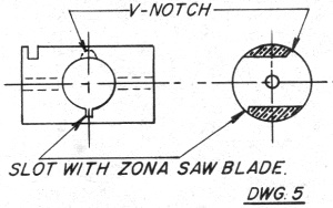
fashions: (1) File a notch on the top side of the throttle barrel as appears on K&B
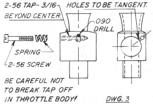
and Veco engines - Dwg # 2; (2) Drill an idle air bleed hole in the front of the carburetor
body in the location shown, such as done by Harold deBolt - Dwg. #3; (3) Make a screw
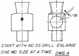
adjustable idle air bleed as used on O.S. Max and Merco engines - (Dwg. #4).
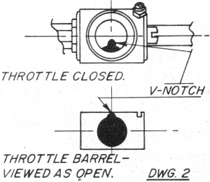
Once you have decided on one of these systems, or if it is already provided, idling
tests can commence. In the following, we will refer to filing the V-notch and the operation
is analogous to the other two, drilling the hole larger or opening up the bleed screw.
In the deBolt system, start with a #55 drill and proceed one drill size at a time.
Take off the exhaust damper or disconnect it and wire it wide open. Start your engine
and slowly retard the idle. If it begins to rich en up and quit, remove the throttle
barrel and increase bleed area by filing the idle notch deeper and wider with Swiss pattern
files - take a few swipes at a time. Start the engine up again and repeat the following
procedure, filing a bit at a time - do a neat job-file symmetrically and watch the file
so that metal is not removed on the opposite side of the barrel. Repeat the procedure
as many times as necessary until the engine idles fairly well at between 2,800 and 3,300
R.P.M. Do not judge R.P.M. at this point by ear as it is very deceiving with the throttle
damper removed. In our tests, we had one of the new General Radio Strobotacs which a
local company loaned us. Use a tachometer of some sort. If using a reed type tachometer
(Vibra-Tak) try to have it checked somewhere first. Accuracy at lower ranges should be
within 200 R.P.M. of a known standard.
Back to the battle. While the engine is idling fairly well at the aforementioned speed,
accelerate it and decelerate it. It is not necessary to do this any faster than a servo
does, not instantaneously anyway. Chances are the engine will decelerate okay, but may
quit on acceleration while tossing off some smoke from the exhaust. This is an indication
that the engine is loading up on idle so make the V-notch a bit larger and continue until
the engine goes up and down fairly well. During this operation, do not touch the needle
valve as set for full power on the rich side. Also do not make any attempt to get lower
than 2,500 R.P.M. or the plug will probably cool off. Also, if you keep filing past the
point where the engine idles well, it will die out due to lack of fuel suction and this
is remedied by filing a very small V-notch (1/32" deep) 180° degrees from the first one,
on the opposite side, to increase suction at the throttle and richen the mixture.
Bolt on or connect the exhaust damper and idle your engine again. Generally, you will
experience an additional 200 to 300 R.P.M. drop. If the engine strangles to a stop, the
damper is fitted too tight and prevents some exhaust leakage which is remedied by opening
the damper a hair or otherwise fitting it looser. Conversely, if the engine R.P.M. does
rise, then tighten up on the exhaust damper to cut down leakage.
"Idling Secrets" will be concluded in December issue of American Modeler
* The editors advise us that this valuable report will be presented
in updated form in the forthcoming American Modeler ANNUAL for 1963 which goes on sale
November 15.
Articles About Engines and Motors for Model Airplanes, Boats, and Cars:
Posted December 17, 2011
|