|
Multi-cylinder model aircraft engines add an incredible degree of
'wow factor' to any model, whether inline, opposed, or radial. From
a functional perspective, multi-cylinder engines are notable smoother
in operation because when properly configured the pistons are moving
in opposite directions and therefore tend to cancel each other's
mass acceleration. More cylinders gets more vibration cancellation.
Torque effects are the same as for any equivalent displacement engine
as engine speed changes. The other great advantage of a multi-cylinder
engine is better idling characteristics. Producing a multi-cylinder
engine take more than simply coupling two or more engines to the
same thrust line since timing issues, even with glow engines than
have no separate ignition systems, perform better when the entire
engine is designed to coordinate all cylinders. This article covers
many different configurations. Who wouldn't like any one of these
babies sitting on display?
Multi-Cylinder Engines
It is a known fact that vibration all but disappears when
another cylinder is added. In his research and development, the
author also achieved low dependable idle. Explained are the results
obtained from various arrangements-feasible if you can use tools.
By William Woodall
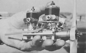
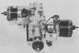
Linked-together engines of different displacements
may be the ideal, Bill believes. This example consists of a McCoy
.35 cylinder in front, with McCoy .19 for rear. Separate crankcases
as well as carburetion.
Photos by Lane Bros. and John Schneider.
A new era for RC flying is here. First is the improved airplane
capable of unbelievable speeds and maneuverability, yet docile enough
to land at reasonable speeds. Second, the excellent proportional
radio equipment now available makes intricate and precise maneuvers
possible. Third, improved RC engines give the airplane performance
and respect far more than once thought possible.
In the field of model engines there are mainly two improvements
to be sought. One - less vibration; two - low, dependable idling.
Like "the jewels of the sea" we have the "jewels" of the model engine
industry at our finger tips just waiting to be developed.
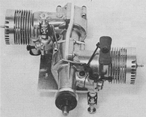
Examples of alternate firing experiments, Mac
.35-.19 (above), and two O.S. 30's (below) which indicate better
idling, linear throttling compared to simultaneous-firing opposed
twins. Separate tubing from bottom of tank to each carburetor a
necessity. There are no starting difficulties; fuel consumption
about equal to equivalent single.
I will endeavor, though crudely, to present a method by which
certain standard single cylinder RC engines can be joined to form
multi-cylinder engines, along with various combinations of displacements
and firing orders. The following classification will indicate those
combinations under consideration.
1) Alternate-firing twin-cylinder engines of equal and unequal
displacement; 2) Simultaneous-firing (opposed) twin-cylinder engines
of equal and unequal displacements; 3) Alternate-firing three-cylinder
engines in-line - that is, one cylinder behind the other - of equal
or unequal displacements.
Two things are to be gained from the end results of joining two
smaller engines together. They are: 1) Less vibration, 2) Lower
dependable idling. One does not gain more power than expected from
equal total displacement as compared to a single engine.
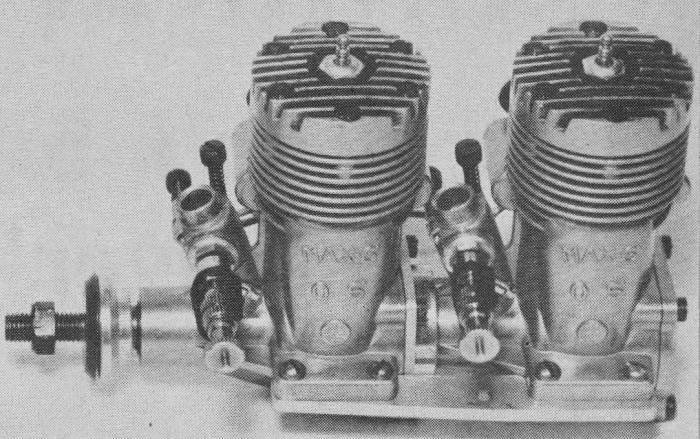
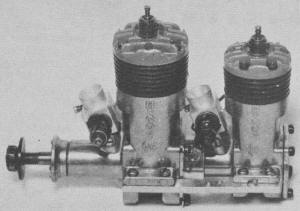
Simultaneous opposed twins, two Max .30's.
Classification 1: Several alternate-firing engines were joined
(each cylinder firing at exactly 180 degrees to the other); in other
words, each cylinder fired once every time the prop made one complete
revolution. The first engine was of equal displacement using two
O.S. Max RC .30's. The next alternate firing engine was of unequal
displacement - a .35 McCoy RC with a .19 McCoy RC in the back position.
Both combinations ran smoothly and idled nicely.
Classification 2: By separating the two alternate-firing engines
and rotating them 180 degrees and re-assembling, I formed two simultaneous-firing
engines - both combinations ran smoothly but, there was an obvious
difference in dependable idling. These engines would not idle as
low as the alternating-firing engines.
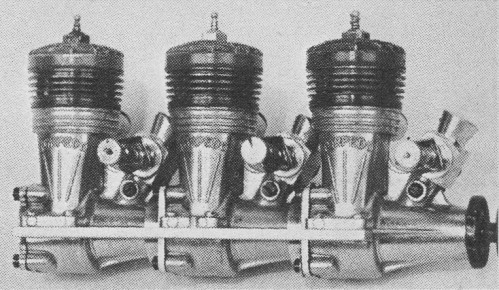
Classification 3: This combination was composed of one K&B
.23 RC and two K&B RC .19's, one behind the other in this order.
The firing order was 1-3-2 cylinders at 120 degrees to each other.
I had to solicit the use of a starter to wind this combination
up. Its "whine" resembles that of a six-cylinder car motor. I see
no real need for this three-cylinder engine at present, but just
wanted to prove to myself that almost unlimited combinations of
engines can be joined together using this method.

Another simultaneous opposed twin, two Max .30's
. These are the same engines used in the assemblies in top photo.
During many hours of flying and bench testing of various combinations
of engines several observations were made in respect to the desired
improvements; they are as follows: 1) Vibration markedly decreased
with both alternating- and simultaneous-firing engines; 2) Dependable
low rpm's in alternate-firing engines is about half that of the
simultaneous-firing engines (these measurements were made with an
electronic tachometer); 3) Linear Throttle - which should be of
particular interest to the rudder-only flyers - where throttle is
elevator.
The alternate firing engine seems to be more promising in the
direction of the "ideal" RC engine. It was also noted that engines
linked together of unequal displacement will tolerate each other
nicely and operate as a unit beautifully. These unequal displacement
combinations may well be the right approach to the "ideal" rather
than the equal displacement combination.
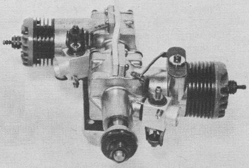
Simultaneous opposed twin, and Mac .35 and .19.
All engines used in these tests were standard RC engines - of
course, their crankcase pressures, etc. were separate. This setup
certainly has its advantage over a single crankcase where both cylinders
are fed from a common crankcase.
The choice of alternate firing engines in the .60 category tested
thus far is two K&B 29's converted for RC operation. Fuel consumption
is about the same as the average single-cylinder engine of equal
displacement. Using an electronic tachometer with the engine on
a testing bench, 12x5 Top Flite prop, 5 per cent nitro-methane in
3:1 methanol and oil fuel, the following rpm's were noted: dependable
idling was 1300 and top speed 10,500. With hotter fuel I feel sure
top rpm could be raised.
Operation: No combination of engines presented any starting idiosyncrasies
- no more than one finds with the single-cylinder engine. The carburetor
adjustment is not difficult-about the same procedure as would be
followed with single-cylinder engines. I do feel that a separate
carburetor for each cylinder has a definite advantage of providing
finer adjustment to each cylinder's need. Separate tubing from bottom
of tank to each carburetor is a necessity - to prevent one cylinder
from starving the other out and consequently causing the engine
to stop.
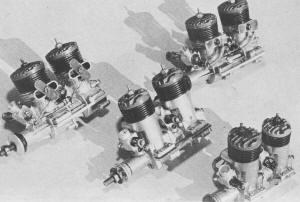
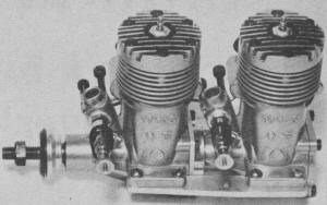
Two K&B .35's (left);
two K&B .29's (upper right); two
McCoy .29's (center); McCoy .35 and
.19 (lower right). Assembly instructions
outlined in text.
Construction: Three parts are to be made: 1) A new back-plate
for the front engine, which is press fitted on the rear engine's
crankcase (made from hard aluminum); 2) A rotor adapter disc which
fastens to the rear engine's crankshaft (made from cold rolled steel);
3) A small pin pressed into the role made in the crank of the front
engine's shaft (made from drill rod).
The rotor adapter disc is fastened to the crankshaft by counter
sinking a hole at desired position into the shaft. An allen screw
(as shown in sketch) is used for this purpose. The threaded part
of the rear crankshaft is removed flush with the rotor adapter disc.
The rotor adapter has a counter-sink to fit the added pin placed
in the front crank hole which links the two crankshafts. This rotor
adapter disc is so placed that after the crankshaft linkage is made,
each crank will be exactly opposite or 180 degrees to the other.
When these parts are in place the engines may be united and fastened
with four backplate screws. A brace made of 1/8" hard aluminum is
bolted on each side to the normal motor mounts, giving added strength
and new mounting areas. I used only one 4-40 bolt with a lock washer
on either side for mounting to the airplane. The linking and adjusting
of the carburetors and exhaust baffles should be made to make the
carburetors and exhaust baffles open and close the same. This has
a decided effect on the idling characteristics of the engine.
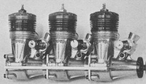
Three K&B .19's confirmed combinations almost
limitless.
Conclusion: My opinion is that the alternate-firing twin-cylinder
engine, equal and unequal displacement combinations, has a definite
advantage over the simultaneous-firing (opposed) engines, only in
better idling, and linear throttle. Vibration tendencies are about
the same.
I have had many hours of pleasure flying these different engines.
All of them have performed well - in the air and on the ground.
I sincerely believe it will be worth your time to construct one
of these combinations and fortunately for those without the necessary
equipment or time, Champion Products, 5620 New Peachtree Rd., Chamblee,
Ga. is now tooling to produce the K&B Twin-29 RC.
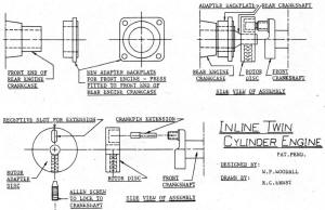
Inline Twin Cylinder Engine Mechanical Drawing.
Articles About Engines and Motors for Model Airplanes, Boats, and Cars:
Posted May 2, 2015
|