|
Even while electric propulsion
systems are gaining ground in the modeling realm, 2- and 4-cylinder engines are
still quite popular amongst modelers. I have made a switchover totally to electric,
but I sure miss the sound and smell of the nitro engines. For those who still use
internal combustion engines, and for those who just want to learn a little more
about how these model engines work, this article by Glenn Lee in the February
1968 issue of American Aircraft Modeler magazine will be a very useful
read.
Inside the Two-Cycle Engine
 By Glenn Lee By Glenn Lee
There's more to a miniature powerplant than meets the eye.
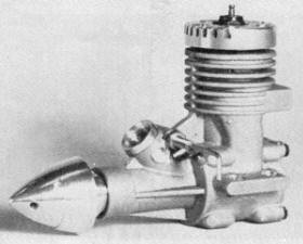
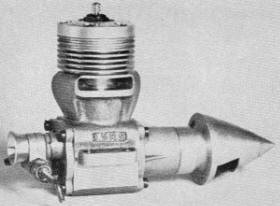
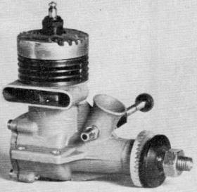
The MVVS 2.5 c.c, glow engine features a rear exhaust, Schnuerle
porting, ball bearings and a crankshaft rotary valve intake.
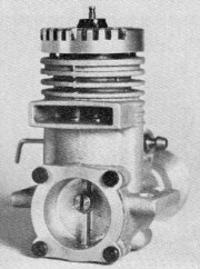
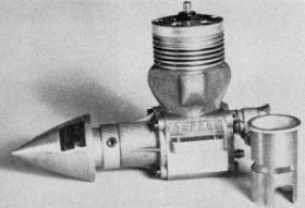
A rear view of the MVVS 2.5 c.c. glow engine. Prototypes of this
engine have placed high in international speed contests.
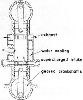
Figure 3: A "double -piston" engine.
The experimental K&B 15RC glow engine built by Bill Wisniewski
and flown to first place in the 1964 World Championships. Bill is famed for his
"tuned pipe" used on speed engines.
Left-side of K&B 15RS with cylinder sleeve shows "lumps"
on case where three ports are located. Piston skirt notched to match lower part
of sleeve.
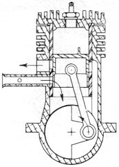
Figure 5: A "side-port" engine. The air intake usually enters
at the rear of the case.
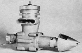
An O. S. 2.5 cc glow engine is an excellent low-priced powerplant.
Features cross scavenging with front rotary valve and bronze sleeve bearing.
A 1966 series K&B .29 high-performance engine has cross scavenging,
ball-bearing crankshaft, and a rear-disk rotary valve intake. Cross scavenging is
used in many engines today.
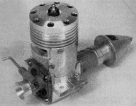
Rear-exhaust 2.5 cc engine built by the author using MOKI crank-shaft,
Super Tigre piston and head, and homemade crankcase and sleeve with Schnuerle porting.
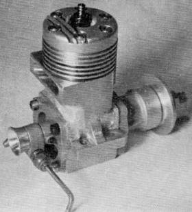
Bypass covers are epoxied and bolted on this .40 cu. in. engine
built by the author. K&B .29 crankshaft and rotary valve used; crankcase machined
from bar stock.
MANY test articles have been written about engines, but few have explained many
of the terms used. Almost all model engines used today are two-cycle; that is the
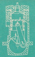
engine fires every revolution. (See Fig. 1.) They are much simpler than four-cycle
engines since they have no oil pumps, timing gears, camshafts, or head valves. They
have their own problems, however, and this article will try to explain some of the
design differences in engines available today and yesterday. Two-cycle engines:
First, consider the methods of getting a fresh charge of fuel and air into the cylinder
and the exhaust gases out. The four strokes use an entire revolution of the crankshaft
to pump the exhaust gases out and draw in a fresh charge. This pumping process results
in a large frictional loss within the engine. In the two strokes, the charge is
allowed in and the exhaust out during the lower part of each revolution. This results
in a loss of power stroke and also mixes the fresh charge with part of the just-fired
charge.
The two-stroke engine also labors from "crankcase scavenging." The crankcase
is sealed, and the up and down travel of the piston acts like a pump to give positive
and negative pressure in the crankcase. Valves are used to allow a fresh fuel-air
charge to enter the case when the piston is going up. The valve is then closed and
the downward travel of the piston compresses the charge. When the piston opens the
bypass port, this compressed charge is directed up into the cylinder. As shown in
Fig. 1., the exhaust port usually opens just before the bypass port and allows the
burned gases to get out with a minimum of mixing with the fresh charge. This is
"cylinder scavenging." Several different methods of scavenging will be discussed
later.
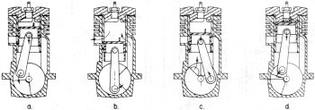
Figure 1: The two-cycle sequence.
a. Air intake is closed, piston is compressing the crank-case charge.
b. Bottom of stroke. ports open. cylinder scavenging tokes place.
c. Piston is drawing in a fresh charge as it compresses the cylinder
charge. Combustion tokes place. air intake is almost closed again.
Since the crankcase acts as the fuel pump, lubricating oil must be mixed with
the fuel. The fuel is vaporized, and a layer of oil is left on all surfaces. Most
of the oil goes through the crankcase and is burned in the cylinder or blown out
the exhaust. This system is simpler than any pressure oil system, and you get an
oil change every revolution. The cylinder walls are lubricated very well this way,
resulting in low friction and long life.
The oil mist lubrication, however, does reduce the amount of fuel-air mixture
we can get into the cylinder. Bearings do not always get an adequate supply of oil,
and sleeve type bearings must be very loose. Scavenging: Going back to cylinder
scavenging, there are several different designs regularly used as diagramed in Fig.
2. All of them use an air blast coming through ports in the cylinder walls to force
the exhaust gases out. Some names given to these methods of scavenging are: Uniflow,
double-piston, cross, and loop. There are several variations of loop scavenging:
Schnuerle, Curtis, reverse loop, and laminar flow.
The uniflow engine has the cylinder, and gases flow only one way. The fresh charge
coming in just above the piston pushes the exhaust gases out the top. Some method
must be used to open the valve at the proper time, such as a cam and rocker arm.
Many years ago, Dooling experimented with an engine using a rotary valve in the
head driven by a gear train, but was troubled by seizing problems due to high temperature
exhaust gases.
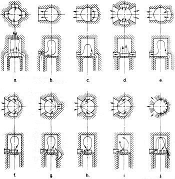
Figure 2: Types of scavenging.
a. Uniflow,
b. Loop,
c. Cross,
d. Original Schnuerle,
e. Laminar,
f. Schnuerle,
g. Schnuerle with a boost port,
h. Reverse loop,
i. Swirl,
j. Curtis.
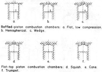
Figure 4 - Cylinder configurations
Cross scavenging is the type used in many engines sold today, such as McCoy,
K&B, Fox, and O.S. Cross-flow engines have the bypass ports located on one side
of the cylinder and the exhaust ports on the opposite side. The piston has a deflector
baffle on the top to deflect the in-coming charge up into the top of the cylinder.
The cross-flow engines have several minor disadvantages. The piston baffle is
directly in the combustion chamber, and disturbs uniform combustion. It also overheats
and distorts the piston. In fact, the baffle on speed engines usually gets melted
away by ultra-high nitro content fuels. There is also a tendency toward a loss of
the fresh charge out the exhaust port, with a resulting loss of power and economy.
A modification of the cross-flow design is the laminar-flow engine, notably the
Super Tigre with its patented bypass port system. In this design, the top edges
of the bypass ports are beveled with a double angle such that the air does not break
away from the cylinder wall. The fresh charge flows around the bevel and is directed
up into the cylinder. The piston top can now be flat, resulting in a uniform combustion
chamber, and heat distortions on the piston are minimized.
The loop scavenged engines have the bypass ports located to direct the fresh
charge against the wall opposite the exhaust port. The charge then loops up into
the cylinder, forcing the exhaust gases down the opposite side and out.
The original Schnuerle system used four ports. The bypass ports were on opposite
sides of the cylinder and the exhaust ports were between them. The charge came through
the bypass ports, met in the center, and then traveled to the top of the cylinder.
The exhaust gases were forced down the sides. Several brands of engines have been
built using this system - well-known engines, too.
Better results were obtained using a single exhaust port with the bypass
ports located on each side of the exhaust and directed toward the opposite
cylinder wall. The latest MVVS engine uses this system. Bill Wisniewski's
engines with which he won the last two World Championships used Schnuerle porting with a small additional
port opposite the exhaust port. This is called a boost port, uses a laminar flow
bevel at the top edge, and directs a charge from under the piston up the cylinder
wall. The newest Cox Mark II also uses a similar system.
One additional benefit from the Schnuerle porting is improved idling characteristics
for RC or other throttle operation. In a cross scavenged engine, the wet fuel charge
is directed at the glow plug. At rich settings and low rpm this wet charge puts
out the glow plug and the engine stops. With loop scavenging the charge loops past
the filament, and the engines can run at very rich, slow settings with-out stopping.
The Curtis scavenging uses multiple ports. The ones opposite the exhaust have
laminar flow top edges while the others direct the flow away from the exhaust similar
to the Schnuerle system.
The reverse-loop scavenging has two bypass ports that direct the fresh charge
just above the exhaust port. The charge loops up that cylinder wall, down the side
opposite the exhaust, and across the top of the piston. A slight variation to this
is the swirl scavenging where one port is directed above the exhaust port and one
is directed against the wall opposite the exhaust port. This results in a rotating
charge giving high turbulence in the cylinder.
The double-piston engine shown in Fig. 3 has two cylinders with a common combustion
chamber and two crankshafts geared together. The inlet ports are located in one
end of the cylinder and exhaust ports in the other. By properly phasing the pistons,
the exhaust ports can open before the inlet ports, and also close before the inlet
ports. The exhaust gases can be cleared with a minimum loss of fresh charge. Complications
are the gears and the double height of the engine. Vibration is minimized, however.
Porting: The biggest problem of scavenging two-cycle engines
is to separate the exhaust residue and the incoming fresh charge. In most engines,
the exhaust port opens slightly ahead of the bypass port. The rapid rush of the
exhaust gases from the cylinder can cause the pressure in the cylinder to drop below
atmospheric, and the resulting vacuum can draw part of the exhaust back into the
cylinder.
If the exhaust port opens too soon, part of the incoming fresh charge can be
lost out the exhaust. The pressure in the cylinder is very high during combustion,
and very little time is required to let these gases out when the exhaust port opens.
The crankcase pressure, how-ever, is very low, on the order of six pounds per square
inch. This low pressure cannot force the fresh charge into the cylinder very fast,
so the bypass ports must be raised or widened to improve performance.
The exhaust port must open before the bypass port, so it must be raised along
with the bypass port. The portion of the wall given to porting must be subtracted
from the working stroke. So, the height of the ports must be matched to the rpm
range at which the engine will be run and also to the burning rate of the fuel used.
Racing engines using high nitro content fuels have very high, wide ports, while
stunt or sport engines have much lower ports.
Port opening periods are usually noted as so many degrees of crankshaft rotation.
This is "exhaust timing" and "by-passing timing." For speed engines the best exhaust
timing has been found to be near 140 degrees, which means that the piston starts
to uncover the exhaust opening when the crankshaft is 70 degrees from bottom dead
center and closes when the crankshaft is 70 degrees past bottom dead center. Bypass
timing varies from 120 to 130 degrees. The Super Tigre engines have symmetrical
timing, the exhaust and bypass open simultaneously. The high pressure of the exhaust
gases holds the fresh charge in the crankcase until the majority of the exhaust
has gone out the exhaust port and pressure in the cylinder has been reduced below
that of the crankcase. This gives the same effect as opening the exhaust port before
the bypass yet allows a higher, larger bypass port to be used.
To improve scavenging in the cylinder, the main factors are time and the amount
of fresh charge that you can get in. At 24,000 rpm, the bypass port is open for
less than 1/1000 of a second. This is not enough time to allow a fresh charge to
travel from the lower part of the crankcase all the way up into the cylinder. The
top of the bypass chamber in the crankcase must be large enough to store a charge
until the piston opens the port, letting the charge into the cylinder quite quickly.
Crankcase passages must be as large as possible to allow unrestricted flow of
gases. On the other hand, this reduces crankcase pumping efficiency and can be detrimental
to high speed performance. It has been found that the best solution to this problem
is to "pack" the crankcase as much as possible, yet leave a large chamber right
next to the bypass ports. Some engines, notably the Dooling, have transfer passages
cut through the wall of the piston to allow the charge to travel into short, curved
bypass passages. This also allows fresh charges to cool the inside of the piston
a little better.
One of the greatest improvements in engine design in the last years has been
the metallurgy of the sleeve-piston combination. The leaded steel sleeve and hardened
cast iron piston is hard to beat, although chrome plating is still being experimentally
used. A chrome plated sleeve is almost a necessity for top performance from a ringed,
aluminum piston engine since friction is very high between aluminum and steel.
Pistons: Pistons, whether iron or aluminum, must be as stiff
as possible to minimize warping and heat distortion. The best pistons have annular
rings inside just above or below the wrist pin holes which aid in keeping them round.
This greatly increases the cost of manufacture, but is usually necessary for high
performance.
Even with a properly designed and manufactured engine, proper break-in of the
sleeve and piston is required. Many attempts have been made to minimize or
eliminate break-in running, but few methods are successful. For best performance, both the
cylinder and the piston should be as round as possible and have the proper clearance
to start with. Lapping the piston in its sleeve with some kind of abrasive compound
usually results in a ruined engine since softer parts of the sleeve get cut deeper
than harder areas. Also, the harder piston will force the abrasive into the soft
metal of the sleeve; it does not get washed out, and will most likely cut too much
clearance during the first runs.
Heating of the piston is not uniform during running, since intensely hot combustion
gases heat the top causing it to expand more than the rest of the piston. The metal
near the top of a lapped piston must be worn away to allow for this expansion before
peak performance can be reached and maximum nitro fuel can be used. This metal worn
away amounts to several thousandths of an inch off the diameter. Some of it can
be ground away before running, but it is easy to grind too much unless you really
know what you are doing. The piston also develops a bulge on the hotter exhaust
side which must be worn away. Larger engines have used asymmetrical "earn-turned"
pistons where this metal was ground away before assembly. It again is very difficult
to grind the proper amount from a piston of the size we use.
The two stroke engines run very hot, and air cooling is usually uneven and inadequate.
The main cooling is from the fresh air and fuel coming into the crankcase. Most
high performance engines use a "hanger" type cylinder sleeve supported only by the
lip at the top. The aluminum crankcase expands more than the sleeve, and even though
it may expand unevenly, it does not squeeze the sleeve out of shape. Warped cases
or warped sleeves are usually the greatest detriments to engine performance.
The importance of proper break-in cannot be overemphasized. Engines on the bench
should be run at or slightly above the rpm that they will operate at in the air.
A smaller diameter, lower pitch prop allows the engine to be run at operating rpm
with a rich needle valve setting. The excess fuel mixture keeps the engine cool
and lubricated to prevent tight parts from seizing.
One other aspect of proper break-in has to do with the instability of some
piston materials. Hardened cast iron is unstable and will actually grow in
dimension when it is heat cycled. This growth can be as much as .001" per inch
of diameter. As an engine is run, the piston is heated and cooled during every
stroke, resulting in a slow growth. This growth, however slight, must be worn
away, and the engine is not broken in until the piston has stabilized. The time
required for this varies according to the heat treatment and the alloy and can be several hours of high
rpm running.
Head Design: Various head shapes are shown in Fig. 4. The classic
domed piston and hemispherical or matched combustion chamber has almost totally
been replaced by fiat top pistons and "squish band" heads. The squish band is a
circular band that fits very close to the piston at top dead center, and "squishes"
the trapped charge into a central combustion chamber. The diameter of the chamber
is usually about 65% of the bore diameter, and the depth is varied to give the correct
compression ratio. A variation of the squish band head is the "trench" head, where
the combustion chamber is a trench milled straight across, leaving wide squish flats
on each side.
If the squish band is too close to the piston, a hydraulic lock can occur.
That is, part of the fuel charge cannot get squished out of the way in time and
is trapped. Extreme compression ratios result in the squish areas, and the result is erratic
running and broken conrods. One way to relieve this problem is to give the squish
band a slight angle relative to the piston; three degrees seems to work.
Squish band heads do have an effect on the allowable nitro content of racing
fuels. Nitro contents as high as 70 and 80 % have been used without detonation.
Many other head shapes have been tried, such as the trumpet head in the
"Rattler" engines, but compression ratio seems to make a bigger difference than
head shape. Compression ratios as high as 18 to one have been used, but few glow
plugs will stand up to such punishment. The compression ratio must be matched
not only to your fuel, but to the weather as well. Test running and test flying is the only way
to find the proper combinations.
Air Intake: So far, we have talked about cylinder-piston combinations
and head shapes, but we must also have an efficient means of getting fuel and air
into the engine.
The simplest method of air induction is the "side port" system as shown in Fig.
5 where the intake port is uncovered by the piston skirt when the piston nears the
top of its stroke. A pipe leads from the needle valve to the port, and when the
port is opened by the piston skirt, the vacuum in the crankcase draws in the fresh
charge. Many model engines have been built this way, but better results are obtained
by rotary valves.
Some engines have been built using reed valves. These are simply a one-way valve
formed by flat, thin, spring steel or beryllium copper reeds. When the piston goes
up, negative pressure opens the reed allowing the fresh charge to come in, and when
the piston starts down the reed closes. Disadvantages to this system are that the
intake timing cannot be controlled, and the engine can also run in either direction.
The best, yet most complicated and most expensive system is the rotary valve.
There are several types, but all of them use a rotary shaft or disk to open and
close the air intake hole at the proper time. The simplest rotary valve is the hole
through the crankshaft that valves the fuel and air into the crankcase through a
port in the main bearing. One advantage to this system is the oil mist cooling of
the crankshaft and bearings. The disadvantage is that the crankcase compression
cannot be very high with the large hole in the crankshaft. Oversize bearings must
also be used.
The rear rotary valve is a disk or drum that is rotated by the crankpin. A large
segment of the disk is cut away to allow passage of fuel and air, and opens and
closes the intake port as it is rotated. Different manufacturers use different intake
timing, but usually the valve opens after the crankshaft has rotated 35 to 45 degrees
past bottom dead center and closes near 45 degrees after top dead center.
Much has been written on hop-up procedures where techniques are stressed on polishing
all air passages, but this can sometimes give a reduction of performance. Oil from
the fuel will stick to a highly polished surface while it can be swept away from
a rougher surface. If it sticks and piles up in the bypass, the result will be a
smaller passage for air flow. Any gain from polishing is usually from the removal
of metal, giving a larger passage.
I hope this article has explained a few of the principles of two-cycle engines
without antagonizing anyone. I have purposely neglected such things as superchargers
or tuned systems. Most engine designs are many years old, but there should be room
for more development of the basic systems. Titanium pistons, for example, do not
work, but bushed titanium conrods are already being used. Such metals as beryllium
and single crystal iron must be tried for pistons or sleeves. Much experimental
work is left.
Articles About Engines and Motors for Model Airplanes, Boats, and Cars:
Posted August 24, 2022
(updated from original post on 6/18/2011)
|