|
Like the Wankel rotary engine, the
horizontal piston engine seems like a good idea on paper. Both engines were masterpieces of
outside-the-box thinking, and were successfully implemented in both prototype and production.
Unfortunately, both engines suffered from technical issues that ultimately excluded them from
being widely adapted. This report on the Aero 35 horizontal piston engine appeared in
a 1964 edition of American Modeler, and also happens to be the year (maybe the only
year) that it was available from its manufacturer, Aero Research and
 Development, of Buffalo, New York. The ingenuity that
went into designing and implementing this engine is amazing. Here is an incredibly in-depth
analysis on the
Aero 35 on the Model Engine News website that is worth your time reading if you want
more details on how the engine works and how an actual example performs. Development, of Buffalo, New York. The ingenuity that
went into designing and implementing this engine is amazing. Here is an incredibly in-depth
analysis on the
Aero 35 on the Model Engine News website that is worth your time reading if you want
more details on how the engine works and how an actual example performs.
Netzeband Reports on the Aero 35 Horizontal Piston Engine
The dream of numerous powerplant experimenters seems to have come true with the Aero 35;
Wild Bill gives you his personal reaction.
 At infrequent intervals during the life of our hobby
someone takes an outstanding technological step upward. The Aero 35 is an example. We went
to the Buffalo plant for the following observations. At infrequent intervals during the life of our hobby
someone takes an outstanding technological step upward. The Aero 35 is an example. We went
to the Buffalo plant for the following observations.
Mr. Auggie Savage and John Piston (who better to design engines?), worked 20 years and
built 45 test engines before obtaining the perfection necessary for a production version.
This engine has been thoroughly bench run, endurance checked, crash and flight tested.
Basic desire behind the departure from standard was a truly streamlined engine, to be used
by scale builders and special types. However, the engine is also exceptionally vibration free.
Since the piston reciprocates parallel to the shaft, its vibration is applied along the fuselage,
rather than normal to thrust line. It is quite easy and natural to absorb this vibration.
R/C and Stunt types will reap benefits from this. The engines we ran at the plant were exceptionally
smooth, compared to the finest balanced standard engine.
The basic transfer motion of piston reciprocation to crankshaft rotation is unique, but
not radical. It is well engineered, based on sound geometry and entirely practical. It goes
something like this.
Connecting rod is an L shaped part with connection into the piston via a slipper block,
a ball socket mating with a fixed bearing in the crankcase and a pin bearing through a slanted
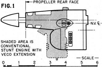
hole in the crank shaft (see sketch). In the piston joint, 3 degrees of freedom exist - vertical
rotation, vertical linear motion and horizontal rotation. Simply stated, the piston pressure
forces bottom end of rod (1) to move in an arc about the ball socket (2). Geometry is established
to minimize the vertical travel of (1). This motion is translated into vertical force at the
crankpin (3), which becomes rotary motion since the pin is restrained by the shaft.
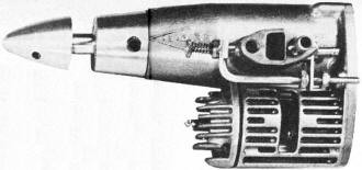
 "A brand new concept In miniature two-cycle engine
design" sez WBN. This version Illustrated at the right is the R/C Throttle model. Look for
smaller and larger motors from same outfit. "A brand new concept In miniature two-cycle engine
design" sez WBN. This version Illustrated at the right is the R/C Throttle model. Look for
smaller and larger motors from same outfit.
Actually this same force transfer pattern is applied in a conventional engine, except the
Aero formula translates it another 90°. Ball joint (2) is on shaft center line so the
crank pin travels as an element of a cone (sweeping about·300). The bottom end (1) travels
vertically approximately 0.050" total and the piston rotates about 10° each side as the
plane surface (1, 2. 3) reciprocates. These slight extra motions do not appear to decrease
power and all points of wear and strain have been adequately designed.
Bore/stroke ratio is 1.21, which is in line with racing configuration. However, intake
bore of 0.177 inch diameter (0.0246 sq. in. area) is in line with stunt design. Intake shaft
timing and cylinder port timing are conservative to make the engine easy to operate for everyone.
Compression ratio is a mild 8:1. Basic version performance typical of stunt 35 performance,
10,000 rpm on 10x6. Top Flite, mild fuel. However, there are tremendous possibilities here
for hop-up.
Construction: Basic crankcase is a one piece aluminum die casting. Alloy steel cylinder
liner is accurately located and cast into the case giving intimate physical contact for best
heat transfer and rigidity. Shape and method of coring yields a clean casting with very little
flash, which is neatly trimmed. Shaft end is precision machined to receive ball bearings with
a light press. Cylinder cooling fins are cast in a line parallel to crankshaft center line.
Twin exhaust ports are vertical and normal to engine center line.
The Aero 35's crankshaft departs from standard practice in several ways. It is machined
from 2024-T4 aluminum bar stock. The thru portion is ground to 3/8" diameter to press lightly
thru the ball bearings. Rear portion has a concave cavity, an angular hole with pressed-in
bronze bushing to receive the connecting rod pin and a milled recess to form the intake rotary
valve. Rear diameter is ground to close tolerance since it runs in close contact with crankcase
walls.
Static balance is simply effected by drilling a (3/16) diameter hole along side the rod
bearing. The wall is relieved, except around the intake port which has a raised machine pad
to effect sealing. Forward end contains a flat which registers the 1/4-28 set screw that locks
the propeller drive shaft. Prop drive shaft is a 2024-T4 screw machine part utilizing a 5/16
shaft. Rear boss carries through the crankcase diameter, smoothly fairing this line. Prop
nut is an aluminum piece shaped and threaded to mate with prop shaft. It is tightened with
a 1/8 diameter rod through a drilled hole. Total effect of front end is a continuous streamlined
shape requiring no spinner.

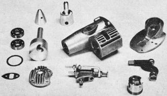
The innards of the Aero 35 tested by Netzeband. Note crankshaft shape,
connecting rod on right. simple throttle in foreground, twin ball-bearings and neat castings.
Ten and one-half ounce powerplant sells for $34.95.
The cylinder head is an aluminum die cast part, utilizing four 4-40 attaching screws, an
asbestos-composition gasket and receiving a long reach glow plug. Internally the head fits
into the cylinder forming a cone-shaped combustion chamber.
The piston is an aluminum die casting. Machining consists of 2 annular ring grooves, OD
grind, and a 7/16" dia. reamed hole to receive the rod slipper block. Perfect Circle piston
rings are installed. Piston is flat top configuration with no baffle plate or dome shaping
involved. Stiffness is assured by cast-in webs and relatively husky side walls. Piston rings
are installed with fairly high expansion loading, so the manufacturer recommends rich running
for the first hour until the rings wear in. Top bypass is directly into crankcase, the other
is on bottom of engine. Fuel transfer distance is much shorter than on conventional mills.
The back plate is an aluminum die casting. It contains a pressed-in ball socket of special
sintered-oil impregnated porous bronze to support the transfer point of the connecting rod.
The mating surface is precision machined to flatness and the assembled joint requires no gasket.
The backplate reaches into the crankcase, effectively packing the unused area for highly efficient
fuel transfer. Engine is mounted by two #6-32 screws into a firewall type mount. Backplate
also contains a screw adjustment for final assembly of connecting rod.
The connecting rod, which is the heart of this engine, is an "L" shaped 4130 steel forging,
heat treated for extra strength (see sketch). Piston-end connection is through a 5/32 diameter
hole and a roll pin thru the slipper block. At the transfer point a precision ball is pressed
onto the rod, and the crankshaft pin is precision ground to 7/32" dia. The slipper block is
machined from alloy steel ground stock, receiving a longitudinal milled slot and a radial
5/32" diameter hole. The roll pin supporting the rod is pressed into the slipper block, so
all motion occurs between hardened steel surfaces of roll pin and connecting rod.
The intake body is extremely well designed featuring a clean-unobstructed venturi throat
connected on each end to rectangular opening of generous size. The needle valve does not have
the usual small diameter needle, rather it utilizes a tapered end from 0.220 to 0.190 inch
dia. in approximately 0.150". It meters very accurately. Anti-rotation device is a nylon set
screw driven into the side of the needle valve threads. This arrangement allows smooth settings,
and positive lock. Fuel enters the throat thru a 0.018 inch dia. hole. There is sufficient
material to open the venturi throat to 0.25 square (0.063 sq. in. area), which should gulp
enough fuel for any combat or R/R type. Intake body is attached to crankcase with two 4-40
screws with Nylok buttons utilizing a thin composition gasket for perfect sealing. The needle
valve is 2-3/4" from the prop eliminating barked knuckles.
 Piece de resistance is an exceptionally simple and
effective throttle. Basically a rod of 3/16" dia. containing a needle valve down its center
line installed in a hole parallel to the regular fuel inlet. This is parallel to shaft center
line. Fore and aft motion restricts the venturi throat and the throttle needle can be adjusted
for proper low speed mixture. Two Elastic stop nuts adjust open and closed positions. Travel
is same as throat diameter but a simple bellcrank can adjust the throw of your throttle system
to match. The test engines throttled very well, with no foolishness. Piece de resistance is an exceptionally simple and
effective throttle. Basically a rod of 3/16" dia. containing a needle valve down its center
line installed in a hole parallel to the regular fuel inlet. This is parallel to shaft center
line. Fore and aft motion restricts the venturi throat and the throttle needle can be adjusted
for proper low speed mixture. Two Elastic stop nuts adjust open and closed positions. Travel
is same as throat diameter but a simple bellcrank can adjust the throw of your throttle system
to match. The test engines throttled very well, with no foolishness.
So, what have we here? It is different, but with a purpose. The Aero 35 will probably be
scaled up and down, It fits a fuselage 1-5/8" wide and 2-1/2" deep. It is 3.85" from back
to prop. As built, it is docile, rock steady and easy to handle. However, hop-up artists should
be able to make a tiger from her since: the aluminum shaft is easily worked, the bypass distance
is exceptionally short, the bore-stroke ratio is there, the light piston and rings are right
and balance is no problem. The engine has something for all, even if you're just interested
in things excitingly different.
One last note. We just barely have loosened up our sample. It runs easily, starts well
and shows good potential. With a close press deadline we selected to tell you about it right
away. We witnessed factory runs, tach'ed them and observed said running.
The demand for the first engines is brisk, with good reason. You will have to change some
of your ideas on nose shapes, 'cause this engine can be exotically cowled, beside being very
good looking out there in the breeze.
This 10-1/2 ounce engine is $34.95 in regular version, $40.90 with throttle. The patents
in U.S. and 6 foreign countries have been approved. Manufacturer is Aero Research and Development
Co., Inc., 51 Great Arrow Avenue, Buffalo 16, N.Y.
Articles About Engines and Motors for Model Airplanes, Boats, and Cars:
Posted July 11, 2015
|